Lexus NX: Removal
REMOVAL
CAUTION / NOTICE / HINT
CAUTION:
Wear protective gloves. Sharp areas on the parts may injure your hands.
PROCEDURE
1. REMOVE FRONT SEAT ASSEMBLY LH
Click here .gif)
2. REMOVE FRONT LOWER SEAT CUSHION SHIELD
Click here
3. REMOVE FRONT SEAT CUSHION SHIELD LH
Click here
4. REMOVE FRONT INNER SEAT CUSHION SHIELD LH
Click here
5. REMOVE FRONT SEAT HEADREST SUPPORT
Click here
6. REMOVE SEPARATE TYPE FRONT SEATBACK COVER WITH PAD
(a) w/ Seat Heater System:
| (1) Disconnect the connector. |
|
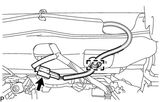
(2) Detach the clamp to disconnect the seat heater wire harness.
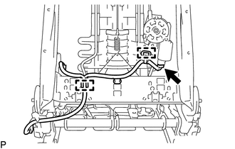
| (b) Remove the 2 nuts to disconnect the 3 seatback cover brackets. |
|
.png)
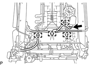
| (c) w/ Climate Control Seat System: (1) Detach the 2 claws to disconnect the duct of the seatback climate control blower. |
|
.png)
(d) Remove the separate type front seatback cover with pad.
7. REMOVE SEATBACK FELT
Click here
8. REMOVE FRONT NO. 1 SEATBACK HOOK
Click here
9. REMOVE FRONT SEATBACK EDGE PROTECTOR
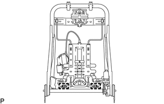
| (a) w/ Climate Control Seat System: (1) Disconnect the connector. (2) Detach the 4 clamps to disconnect the front No. 2 seat wire LH. |
|
| (b) w/o Climate Control Seat System: (1) Disconnect the connector. (2) Detach the 2 clamps to disconnect the front No. 2 seat wire LH. |
|
| (c) Detach the 2 claws and 4 guides to remove the 2 front seatback edge protectors. |
|
.png)
10. REMOVE LUMBAR SUPPORT ADJUSTER ASSEMBLY LH
| (a) Detach the 2 hooks to remove the lumbar support adjuster assembly LH from the front seatback frame sub-assembly LH. |
|
READ NEXT:
 Inspection
INSPECTION PROCEDURE 1. INSPECT LUMBAR SUPPORT ADJUSTER ASSEMBLY LH (a) Check the operation of the lumbar support adjuster assembly LH. (1) Apply auxiliary battery voltage to the lumbar support adj
Installation
INSTALLATION CAUTION / NOTICE / HINT CAUTION: Wear protective gloves. Sharp areas on the parts may injure your hands. PROCEDURE 1. INSTALL LUMBAR SUPPORT ADJUSTER ASSEMBLY LH (a) Attach the 2 hooks to
SEE MORE:
Inspection
INSPECTION PROCEDURE 1. INSPECT WINDSHIELD WIPER SWITCH ASSEMBLY (a) w/o Auto Wiper System: (1) Measure the resistance according to the value(s) in the table below. Standard Resistance: Front Wiper Switch Tester Connection Condition Specified Condition I125-2 (+B) - I125-3 (+1) MIST
Diagnosis System
DIAGNOSIS SYSTEM DIAGNOSIS FUNCTION (a) The road sign assist system displays a warning message on the multi-information display to inform the driver that the system is unavailable when it is malfunctioning. Warning Message Details DTC/RoB "RSA Malfunction Visit Your Dealer" is displayed
