Lexus NX: Seat Heater Switch(for Rear Seat)
Components
COMPONENTS
ILLUSTRATION
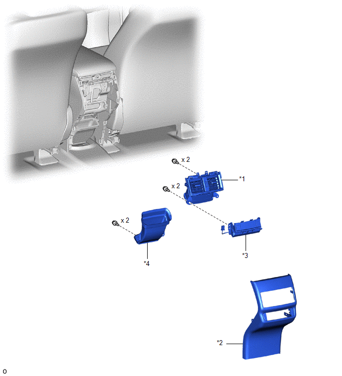
| *1 | CONSOLE BOX REGISTER ASSEMBLY | *2 | REAR CONSOLE END PANEL SUB-ASSEMBLY |
| *3 | REFRESHING SEAT SWITCH | *4 | DUCT |
Removal
REMOVAL
PROCEDURE
1. REMOVE REAR CONSOLE END PANEL SUB-ASSEMBLY
Click here .gif)
2. REMOVE CONSOLE BOX REGISTER ASSEMBLY
Click here
3. REMOVE REFRESHING SEAT SWITCH
| (a) Detach the wire harness of the refreshing seat switch from the hook. |
|
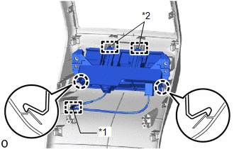
(b) Detach the 2 claws.
(c) Detach the 2 guides and remove the refreshing seat switch.
Inspection
INSPECTION
PROCEDURE
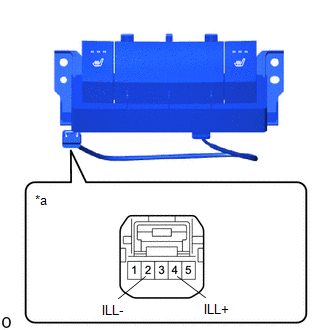
1. INSPECT REFRESHING SEAT SWITCH
| (a) Apply battery voltage to the connector and check that the telltale light assembly indicator illuminates. OK:
If the result is not as specified, replace the refreshing seat switch. |
|
Installation
INSTALLATION
PROCEDURE
1. INSTALL REFRESHING SEAT SWITCH
| (a) Attach the 2 guides. |
|

(b) Attach the 2 claws and install the refreshing seat switch.
(c) Install the wire harness of the refreshing seat switch to the hook.
2. INSTALL CONSOLE BOX REGISTER ASSEMBLY
Click here .gif)
3. INSTALL REAR CONSOLE END PANEL SUB-ASSEMBLY
Click here
4. INSPECT SEAT HEATER SYSTEM (for Rear Seat)
Click here
READ NEXT:
 Precaution
PRECAUTION FOR OPERATION OF ELECTRICAL ITEMS RESTRICTED NOTICE:
If the auxiliary battery voltage is low, the seat heater system may not operate. When "High Power Consumption / Partial Limit On AC/H
Parts Location
PARTS LOCATION ILLUSTRATION *A w/ Rear Seat Heater - - *1 AIR CONDITIONING CONTROL ASSEMBLY *2 SEAT HEATER SWITCH (for Driver Side) *3 SEAT HEATER SWITCH (for Front Passenger
SEE MORE:
Installation
INSTALLATION PROCEDURE 1. INSTALL QUICK HEATER ASSEMBLY (a) Install the quick heater assembly with the screw. (b) Attach the clamp and connect the 2 connectors. 2. INSTALL NO. 1 AIR DUCT Click here 3. INSTALL LOWER INSTRUMENT PANEL Click here
System Description
SYSTEM DESCRIPTION WIRELESS CHARGING SYSTEM (a) The wireless charging system allows Qi-compatible* devices to be charged without the use of a charging cable by placing them on the charging area of the mobile wireless charger cradle assembly. HINT: *: The Qi (chee) standard is an international wirele
