Lexus NX: Removal
REMOVAL
PROCEDURE
1. PRECAUTION
Click here .gif)
2. REMOVE REAR BUMPER COVER
Click here
3. REMOVE NO. 2 LUGGAGE ROOM WIRE
Click here
4. REMOVE REAR CORNER ULTRASONIC SENSOR
| (a) Detach the 2 claws and remove the rear corner ultrasonic sensor. HINT:
|
|
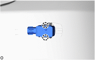
5. REMOVE REAR CENTER ULTRASONIC SENSOR
HINT:
Use the same procedure described for the rear corner ultrasonic sensor.
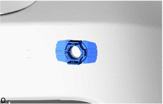
6. REMOVE REAR CORNER ULTRASONIC SENSOR RETAINER
HINT:
- When removing the rear corner ultrasonic sensor retainer, heat the rear bumper assembly and rear corner ultrasonic sensor retainer using a heat light.
- Use the same procedure for both rear corner ultrasonic sensor retainers.
Standard:
| Item | Temperature |
|---|---|
| Rear Bumper Assembly | 20 to 30°C (68 to 86°F) |
| Rear Corner Ultrasonic Sensor Retainer |
NOTICE:
- Do not heat the rear bumper assembly on rear corner ultrasonic sensor retainer excessirely.
- Do not reuse the removed rear corner ultrasonic sensor retainer.
| (a) Remove the rear corner ultrasonic sensor retainer. |
|
7. REMOVE REAR CENTER ULTRASONIC SENSOR RETAINER
HINT:
Use the same procedure described for the rear corner ultrasonic sensor retainer.
8. REMOVE ULTRASONIC SENSOR CUSHION SET
HINT:
Perform the following procedure only when replacement of a ultrasonic sensor cushion set is necessary.
(a) Remove the ultrasonic sensor cushion set as shown in the illustration.
.png)
.png) | Remove in this Direction | - | - |
READ NEXT:
 Inspection
INSPECTION PROCEDURE 1. INSPECT REAR CENTER ULTRASONIC SENSOR (a) Measure the resistance according to the value(s) in the table below. Standard Resistance: Tester Connection Condition Speci
Installation
INSTALLATION PROCEDURE 1. INSTALL ULTRASONIC SENSOR CUSHION SET HINT: Perform the following procedure only when replacement of a ultrasonic sensor cushion set is necessary. (a) Install the ultrasonic
SEE MORE:
Main Switch Circuit
DESCRIPTION When the blind spot monitor main switch (combination switch assembly) is turned on, a signal is sent to the blind spot monitor sensor LH and the blind spot monitor indicator on the blind spot monitor main switch (combination switch assembly) illuminates. The blind spot monitor system ope
Lost Communication with Blind Spot Monitor Slave Module (U0232)
DESCRIPTION This DTC is stored when the blind spot monitor sensor LH judges that there is a communication error with the blind spot monitor sensor RH. DTC No. Detection Item DTC Detection Condition Trouble Area Note U0232 Lost Communication with Blind Spot Monitor Slave Module The
