Lexus NX: Removal
REMOVAL
PROCEDURE
1. REMOVE FRONT WHEEL
Click here .gif)
2. REMOVE NO. 1 ENGINE UNDER COVER ASSEMBLY
Click here
3. REMOVE REAR ENGINE UNDER COVER LH
Click here
4. REMOVE REAR ENGINE UNDER COVER RH
Click here
5. DRAIN HYBRID TRANSAXLE FLUID
Click here
6. REMOVE FRONT AXLE SHAFT NUT LH
Click here
7. REMOVE FRONT AXLE SHAFT NUT RH
HINT:
Use the same procedure described for the LH side.
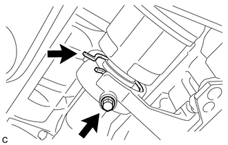
8. DISCONNECT FRONT SPEED SENSOR LH (w/o AVS)
| (a) Remove the clamp. |
|
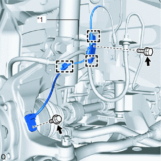
(b) Remove the bolt, 2 guides and sensor clamp from the absorber bracket.
(c) Disconnect the bolt and front speed sensor LH.
NOTICE:
Prevent foreign matter from attaching to the front speed sensor tip.
9. REMOVE FRONT SPEED SENSOR LH (w/ AVS)
(a) Remove the front speed sensor LH.
(Click here )
(b) Disconnect the skid control sensor wire LH.
| (1) Remove the bolt, guide and sensor clamp. |
|
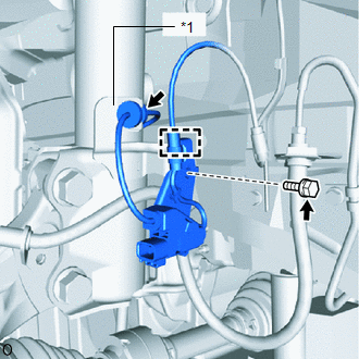
(2) Remove the grommet from the absorber bracket.
10. DISCONNECT FRONT SPEED SENSOR RH (w/o AVS)
HINT:
Use the same procedure described for the LH side.
11. REMOVE FRONT SPEED SENSOR RH (w/ AVS)
HINT:
Use the same procedure described for the LH side.
12. DISCONNECT FRONT STABILIZER LINK ASSEMBLY LH
Click here
13. DISCONNECT FRONT STABILIZER LINK ASSEMBLY RH
HINT:
Use the same procedure described for the LH side.
14. DISCONNECT FRONT LOWER NO. 1 SUSPENSION ARM SUB-ASSEMBLY LH
Click here
15. DISCONNECT FRONT LOWER NO. 1 SUSPENSION ARM SUB-ASSEMBLY RH
HINT:
Use the same procedure described for the LH side.
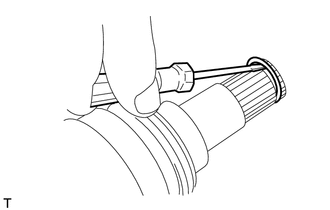
16. DISCONNECT FRONT AXLE ASSEMBLY LH
| (a) Remove the bolt and detach the 2 guides. |
|
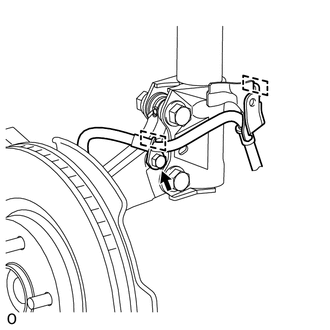
| (b) Put matchmarks on the front drive shaft assembly LH and front axle assembly LH. NOTICE: Do not use a punch to make the matchmarks. |
|
(c) Using a plastic-faced hammer, disconnect the front drive shaft assembly LH from the front axle assembly LH.
NOTICE:
- Do not damage the front axle outboard joint boot and drive shaft dust cover.
- Do not excessively push out the front drive shaft assembly LH from the front axle assembly LH.
17. DISCONNECT FRONT AXLE ASSEMBLY RH
HINT:
Use the same procedure described for the LH side.
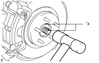
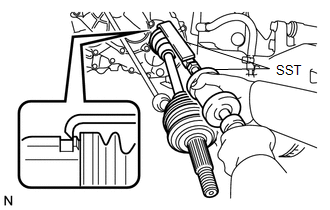
18. REMOVE FRONT DRIVE SHAFT ASSEMBLY LH
| (a) Using SST, remove the front drive shaft assembly LH. SST: 09520-01010 SST: 09520-24010 09520-32040 NOTICE:
HINT: Hook the SST claw at the position shown in the illustration to remove the front drive shaft assembly LH. |
|
19. REMOVE FRONT DRIVE SHAFT ASSEMBLY RH
| (a) Disconnect the drive shaft bearing bracket hole snap ring from the drive shaft bearing bracket. |
|
(b) Remove the bolt and front drive shaft assembly RH from the drive shaft bearing bracket.
NOTICE:
- Do not damage the front drive shaft oil seal RH, front axle inboard joint boot and front drive shaft dust cover RH.
- Do not drop the front drive shaft assembly RH.
- When carrying the front drive shaft assembly RH, hold it horizontally.
HINT:
If the spline connection is stiff, using a brass bar and hammer, lightly tap the inboard joint assembly to remove it.
(c) Remove the drive shaft bearing bracket hole snap ring from the front drive shaft assembly RH.
20. REMOVE FRONT DRIVE SHAFT HOLE SNAP RING LH
| (a) Using a screwdriver, remove the front drive shaft hole snap ring LH. NOTICE: Do not damage the spline of the front drive inboard joint assembly LH. |
|
READ NEXT:
 Disassembly
DISASSEMBLY CAUTION / NOTICE / HINT NOTICE:
When using a vise, place aluminum plates between the part and vise.
When using a vise, do not overtighten it.
PROCEDURE 1. DISCONNECT FRONT NO. 2 AX
Inspection
INSPECTION CAUTION / NOTICE / HINT NOTICE:
When using a vise, place aluminum plates between the part and vise.
When using a vise, do not overtighten it.
PROCEDURE 1. INSPECT FRONT DRIVE SHAFT
Reassembly
REASSEMBLY CAUTION / NOTICE / HINT NOTICE:
When using a vise, place aluminum plates between the part and vise.
When using a vise, do not overtighten it.
PROCEDURE 1. INSTALL FRONT DRIVE SHAFT
SEE MORE:
Hybrid Vehicle Control Ecu
ComponentsCOMPONENTS ILLUSTRATION *1 ECU INTEGRATION BOX RH *2 GLOVE COMPARTMENT DOOR ASSEMBLY *3 HYBRID VEHICLE CONTROL ECU *4 NO. 2 INSTRUMENT PANEL UNDER COVER SUB-ASSEMBLY N*m (kgf*cm, ft.*lbf): Specified torque - - RemovalREMOVAL PROCEDURE 1. PRECAUTION NOTIC
Dtc Check / Clear
DTC CHECK / CLEAR CHECK DTC (a) Connect the Techstream to the DLC3. (b) Turn the power switch on (IG). (c) Turn the Techstream on. (d) Enter the following menus: Body Electrical / Head Up Display / Trouble Codes. (e) Check for DTCs. Body Electrical > Head Up Display > Trouble Codes CLEAR DTC (
