Lexus NX: Repair
REPAIR
CAUTION / NOTICE / HINT
HINT:
- Use the same procedure for the RH and LH sides.
- The procedure listed below is for the LH side.
- If the installation area of the headlight assembly is damaged, use the supply retainer for low-cost repair.
- Make sure that the headlight assembly is not damaged.
PROCEDURE
1. INSTALL UPPER HEADLIGHT PROTECTOR RETAINER RH
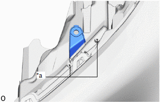
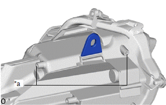
| (a) Cut off the blue-colored part in the illustration and sand smooth with sandpaper. NOTICE: After cutting off the part, place the upper headlight protector retainer RH against the bosses and gradually file away the old bracket if it interferes with the installation of the supply retainer. |
|
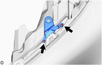
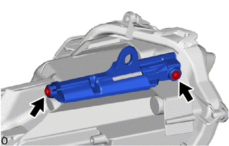
| (b) Install the upper headlight protector retainer RH with the 2 screws. |
|
2. INSTALL UPPER HEADLIGHT PROTECTOR RETAINER LH
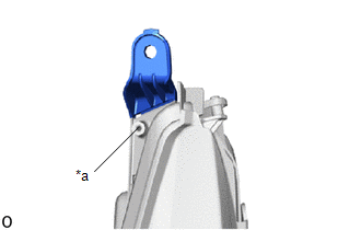
| (a) Cut off the blue-colored part in the illustration and sand smooth with sandpaper. NOTICE: After cutting off the part, place the upper headlight protector retainer LH against the bosses and gradually file away the old bracket if it interferes with the installation of the supply retainer. |
|
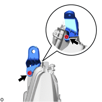
| (b) Install the upper headlight protector retainer LH with the 2 screws. |
|
3. INSTALL LOWER HEADLIGHT PROTECTOR RETAINER LH
| (a) Cut off the blue-colored part in the illustration and sand smooth with sandpaper. NOTICE: After cutting off the part, place the lower headlight protector retainer LH against the bosses and gradually file away the old bracket if it interferes with the installation of the supply retainer. |
|
| (b) Install the lower headlight protector retainer LH with the 2 screws. |
|
READ NEXT:
 Precaution
PRECAUTION NOTICE: When disassembling the headlight assembly, use static electricity countermeasures SST (desktop antistatic mat set) and observe all precautions to prevent damage to the system by ele
Components
COMPONENTS ILLUSTRATION *1 HEADLIGHT ASSEMBLY LH - - N*m (kgf*cm, ft.*lbf): Specified torque - - ILLUSTRATION *A w/ Headlight ECU - - *1 FRONT SIDE MAKER LIGHT
SEE MORE:
Removal
REMOVAL PROCEDURE 1. REMOVE NO. 3 DECK BOARD SUB-ASSEMBLY Click here 2. REMOVE REAR DECK FLOOR BOX Click here 3. REMOVE DECK FLOOR BOX LH Click here 4. PRECAUTION CAUTION: Be sure to read Precaution thoroughly before servicing. Click here NOTICE: After the power switch is turned off, there m
Front Side Marker Light Bulb(for Single Beam Headlight)
ReplacementREPLACEMENT CAUTION / NOTICE / HINT HINT:
Use the same procedure for the RH and LH sides.
The procedure listed below is for the LH side.
PROCEDURE 1. REMOVE FRONT SIDE MARKER LIGHT SOCKET (a) Disconnect the connector. (b) Turn the front side marker light socket cou
