Lexus NX: Seat Heater for Rear Right Seat does not Operate
DESCRIPTION
When the refreshing seat switch is operated, the air conditioning amplifier assembly receives the signal via the LIN communication line, and operates the seat heater for the corresponding rear seat.
WIRING DIAGRAM
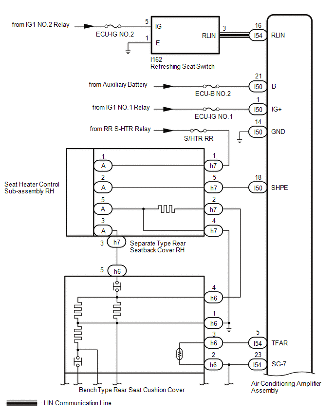
.png)
CAUTION / NOTICE / HINT
NOTICE:
-
If the auxiliary battery voltage is low, the seat heater system may not operate. When "High Power Consumption / Partial Limit On AC/Heater Operation" is displayed on the multi-information display in the combination meter assembly, inspect the auxiliary battery, referring to On-vehicle Inspection for the charging system.
HINT:
If the auxiliary battery voltage is low, "Operation Limitation Control History Count (Level 1)" and "Operation Limitation Control History Count (Level 2) is counted.
Click here
.gif)
Click here
-
If the auxiliary battery voltage is low, the seat heater system may not operate. Refer to Data List for the power steering system.
-
for Manual Tilt and Manual Telescopic Steering Column:
-
for Power Tilt and Power Telescopic Steering Column:
-
for Manual Tilt and Manual Telescopic Steering Column:
- Inspect the fuses for circuits related to this system before performing the following procedure.
-
When the auxiliary battery is disconnected or the air conditioning amplifier assembly is replaced, be sure to perform servo motor initialization.
Click here
PROCEDURE
| 1. | CLEAR DTC |
(a) Clear the DTCs.
Click here
|
.gif)
| 2. | CHECK FOR DTC |
(a) Check for DTCs.
Click here
OK:
DTC B14C2 is not output.
| NG | .gif) | GO TO DTC B14C2 |
|
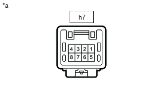
| 3. | CHECK HARNESS AND CONNECTOR (SEPARATE TYPE REAR SEATBACK COVER RH - BATTERY AND BODY GROUND) |
| (a) Disconnect the separate type rear seatback cover RH connector. |
|
(b) Measure the resistance according to the value(s) in the table below.
Standard Resistance:
| Tester Connection | Condition | Specified Condition |
|---|---|---|
| h7-4 - Body ground | Always | Below 1 Ω |
(c) Measure the voltage according to the value(s) in the table below.
Standard Voltage:
| Tester Connection | Condition | Specified Condition |
|---|---|---|
| h7-1 - Body ground | Power switch on (IG) | 11 to 14 V |
| h7-1 - Body ground | Power switch off | Below 1 V |
| NG | | REPAIR OR REPLACE HARNESS OR CONNECTOR |
|
| 4. | INSPECT SEPARATE TYPE REAR SEATBACK COVER RH |
(a) Remove the separate type rear seatback cover RH.
-
for Manual Seat:
-
for Power Seat:
(b) Inspect the separate type rear seatback cover RH.
-
for Manual Seat:
-
for Power Seat:
| NG | | REPLACE SEPARATE TYPE SEATBACK COVER RH |
|
| 5. | CHECK HARNESS AND CONNECTOR (SEPARATE TYPE REAR SEATBACK COVER RH - AIR CONDITIONING AMPLIFIER ASSEMBLY) |
(a) Disconnect the h7 separate type rear seatback cover RH connector.
(b) Disconnect the I50 air conditioning amplifier assembly connector.
(c) Measure the resistance according to the value(s) in the table below.
Standard Resistance:
| Tester Connection | Condition | Specified Condition |
|---|---|---|
| h7-5 - I50-18 (SHPE) | Always | Below 1 Ω |
| h7-5 or I50-18 (SHPE) - Body ground | Always | 10 kΩ or higher |
| NG | | REPAIR OR REPLACE HARNESS OR CONNECTOR |
|
| 6. | CHECK HARNESS AND CONNECTOR (BENCH TYPE REAR SEAT CUSHION COVER - SEPARATE TYPE REAR SEATBACK COVER RH AND BODY GROUND) |
(a) Disconnect the h6 bench type seat cushion cover connector.
(b) Disconnect the h7 separate type rear seatback cover RH connector.
(c) Measure the resistance according to the value(s) in the table below.
Standard Resistance:
| Tester Connection | Condition | Specified Condition |
|---|---|---|
| h6-5 - h7-3 | Always | Below 1 Ω |
| h6-4 - h7-2 | Always | Below 1 Ω |
| h6-1 - Body ground | Always | Below 1 Ω |
| h6-5 or h7-3 - Body ground | Always | 10 kΩ or higher |
| h6-4 or h7-2 - Body ground | Always | 10 kΩ or higher |
| NG | | REPAIR OR REPLACE HARNESS OR CONNECTOR |
|
| 7. | INSPECT BENCH TYPE REAR SEAT CUSHION COVER |
(a) Remove the bench type rear seat cushion cover.
-
for Manual Seat:
-
for Power Seat:
(b) Inspect the bench type rear seat cushion cover.
-
for Manual Seat:
-
for Power Seat:
| NG | | REPLACE BENCH TYPE REAR SEAT CUSHION COVER |
|
| 8. | CHECK SEAT HEATER CONTROL SUB-ASSEMBLY RH |
(a) Temporarily replace the seat heater control sub-assembly RH with a new or known good one.
Click here
OK:
The seat heater operates normally.
| OK | | END (SEAT HEATER CONTROL SUB-ASSEMBLY RH WAS DEFECTIVE) |
| NG | | REPLACE AIR CONDITIONING AMPLIFIER ASSEMBLY |
READ NEXT:
 Seat Heater for Rear Left Seat does not Operate
DESCRIPTION When the refreshing seat switch is operated, the air conditioning amplifier assembly receives the signal via the LIN communication line, and operates the seat heater for the corresponding
Components
COMPONENTS ILLUSTRATION *1 FRONT DOOR INSIDE HANDLE BEZEL PLUG LH *2 FRONT DOOR TRIM BOARD SUB-ASSEMBLY LH *3 FRONT DOOR TRIM COVER LH *4 FRONT SEAT SLIDE SWITCH BEZEL *5 POW
SEE MORE:
Brake Booster Pump Motor on Time Abnormally Long (C1252,C1253)
DESCRIPTION The skid control ECU (brake booster with master cylinder assembly) detects decreases in the accumulator pressure according to the data from the accumulator pressure sensor, and then starts and stops the pump motor by operating the motor relay. DTC No. Detection Item INF Code DTC
Removal
REMOVAL PROCEDURE 1. REMOVE ENGINE OIL LEVEL DIPSTICK GUIDE (a) Remove the engine oil level dipstick. (b) Remove the bolt and engine oil level dipstick guide. (c) Remove the O-ring from the engine oil level dipstick guide. 2. REMOVE V-RIBBED BELT TENSIONER ASSEMBLY (a) Remove the b
