Lexus NX: Sliding Roof ECU Communication Stop (B1273)
DESCRIPTION
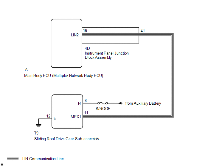
This DTC is stored when LIN communication between the sliding roof drive gear sub-assembly and main body ECU (multiplex network body ECU) stops for 10 seconds or more.
| DTC No. | Detection Item | DTC Detection Condition | Trouble Area |
|---|---|---|---|
| B1273 | Sliding Roof ECU Communication Stop | No communication between the sliding roof drive gear sub-assembly and main body ECU (multiplex network body ECU) for 10 seconds or more. |
|
WIRING DIAGRAM
CAUTION / NOTICE / HINT
NOTICE:
-
When using the Techstream with the power switch off to troubleshoot:
Connect the Techstream to the vehicle, and turn a courtesy light switch on and off at 1.5 second intervals until communication between the Techstream and vehicle begins.
- Inspect the fuses for circuits related to this system before performing the following inspection procedure.
-
When the sliding roof drive gear sub-assembly is removed and reinstalled or replaced, the sliding roof drive gear sub-assembly must be initialized.
Click here
.gif)
- Recognition code registration is necessary when replacing the main body ECU (multiplex network body ECU).
-
If the main body ECU (multiplex network body ECU) is replaced, refer to Registration.
Click here
HINT:
DTC B2325 is output when the communication between all of the following components and main body ECU (multiplex network body ECU) stops.
Click here
PROCEDURE
| 1. | CLEAR DTC |
(a) Clear the DTCs.
Click here
|
.gif)
| 2. | CHECK FOR DTC |
(a) Check for DTCs.
Click here
| DTC B1273 is not output | .gif) | USE SIMULATION METHOD TO CHECK |
|
| 3. | CHECK HARNESS AND CONNECTOR (MAIN BODY ECU [MULTIPLEX NETWORK BODY ECU] - SLIDING ROOF DRIVE GEAR SUB-ASSEMBLY) |
(a) Remove the main body ECU (multiplex network body ECU) from the instrument panel junction block assembly.
Click here
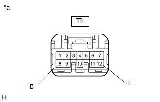
(b) Disconnect the T9 sliding roof drive gear sub-assembly connector.
(c) Measure the resistance according to the value(s) in the table below.
Standard Resistance:
| Tester Connection | Condition | Specified Condition |
|---|---|---|
| A-16 (LIN2) - T9-11 (MPX1) | Always | Below 1 Ω |
| A-16 (LIN2) - Body ground | Always | 10 kΩ or higher |
| NG | | GO TO STEP 7 |
|
| 4. | CHECK HARNESS AND CONNECTOR (SLIDING ROOF DRIVE GEAR SUB-ASSEMBLY - BATTERY AND BODY GROUND) |
| (a) Disconnect the sliding roof drive gear sub-assembly connector. |
|
(b) Measure the resistance according to the value(s) in the table below.
Standard Resistance:
| Tester Connection | Condition | Specified Condition |
|---|---|---|
| T9-12 (E) - Body ground | Always | Below 1 Ω |
(c) Measure the voltage according to the value(s) in the table below.
Standard Voltage:
| Tester Connection | Switch Condition | Specified Condition |
|---|---|---|
| T9-8 (B) - Body ground | Power switch off | 11 to 14 V |
| NG | | REPAIR OR REPLACE HARNESS OR CONNECTOR |
|
| 5. | REPLACE SLIDING ROOF DRIVE GEAR SUB-ASSEMBLY |
(a) Temporarily replace the sliding roof drive gear sub-assembly with a new or normally functioning one.
Click here
(b) Clear the DTCs.
Click here
|
| 6. | CHECK FOR DTC |
(a) Check for DTCs.
Click here
| DTC B1273 is not output | | END (SLIDING ROOF DRIVE GEAR SUB-ASSEMBLY IS DEFECTIVE) |
| DTC B1273 is output | | REPLACE MAIN BODY ECU (MULTIPLEX NETWORK BODY ECU) |
| 7. | CHECK HARNESS AND CONNECTOR (INSTRUMENT PANEL JUNCTION BLOCK ASSEMBLY - SLIDING ROOF DRIVE GEAR SUB-ASSEMBLY) |
(a) Remove the main body ECU (multiplex network body ECU) from the instrument panel junction block assembly.
Click here
(b) Disconnect the T9 sliding roof drive gear sub-assembly connector.
(c) Measure the resistance according to the value(s) in the table below.
Standard Resistance:
| Tester Connection | Condition | Specified Condition |
|---|---|---|
| 4D-41 - T9-11 (MPX1) | Always | Below 1 Ω |
| 4D-41 - Body ground | Always | 10 kΩ or higher |
| OK | | REPLACE INSTRUMENT PANEL JUNCTION BLOCK ASSEMBLY |
| NG | | REPAIR OR REPLACE HARNESS OR CONNECTOR |
READ NEXT:
 Driver Side Door ECU Communication Stop (B2321)
DESCRIPTION This DTC is stored when LIN communication between the front power window regulator motor assembly LH and main body ECU (multiplex network body ECU) stops for 10 seconds or more. DTC No.
Front Passenger Side Door ECU Communication Stop (B2322)
DESCRIPTION This DTC is output when LIN communication between the front power window regulator motor assembly RH and main body ECU (multiplex network body ECU) stops for 10 seconds or more. DTC No.
Rear Door RH ECU Communication Stop (B2323)
DESCRIPTION This DTC is output when LIN communication between the rear power window regulator motor assembly RH and main body ECU (multiplex network body ECU) stops for 10 seconds or more. DTC No.
SEE MORE:
EV drive mode
In EV drive mode, electric power is
supplied by the hybrid battery
(traction battery), and only the
electric motor (traction motor) is
used to drive the vehicle.
This mode allows you to drive in residential
areas early in the morning
and late at night, or in indoor parking
lots, etc., with
Fail-safe Chart
FAIL-SAFE CHART FAIL-SAFE FUNCTION (a) When a malfunction occurs in the pre-collision system, a message will be displayed on the multi-information display and the pre-collision system will be disabled depending on the malfunction. Warning Message Cause DTC/RoB Conditions to Return to Normal
