Lexus NX: System Diagram
Lexus NX Service Manual / Engine & Hybrid System / 2ar-fxe (emission Control) / Emission Control System / System Diagram
SYSTEM DIAGRAM
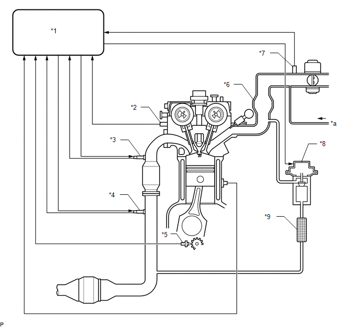
| *1 | ECM | *2 | Engine Coolant Temperature Sensor |
| *3 | Air Fuel Ratio Sensor (for Bank 1 Sensor 1) | *4 | Heated Oxygen Sensor (for Bank 1 Sensor 2) |
| *5 | Crankshaft Position Sensor | *6 | Intake Manifold |
| *7 | Manifold Absolute Pressure Sensor | *8 | EGR Valve Assembly |
| *9 | EGR Cooler Assembly | - | - |
| *a | from Purge VSV | - | - |
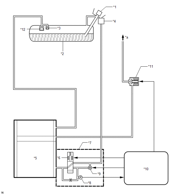
| *1 | Fuel Tank Cap Assembly | *2 | Fuel Tank Assembly |
| *3 | Fuel Cutoff Valve | *4 | Canister Filter |
| *5 | Charcoal Canister Assembly | *6 | Vent Valve |
| *7 | Canister Pump Module | *8 | Canister Pressure Sensor |
| *9 | Leak Detection Pump | *10 | ECM |
| *11 | Purge VSV | *12 | Float Valve |
| *a | to Intake Manifold | - | - |
READ NEXT:
 On-vehicle Inspection
ON-VEHICLE INSPECTION PROCEDURE 1. VISUALLY INSPECT HOSES, CONNECTIONS AND GASKETS (a) Visually check that the hoses, connections and gaskets have no cracks, leaks or damage. NOTICE:
Detachment or
Fuel Tank Cap
InspectionINSPECTION PROCEDURE 1. INSPECT FUEL TANK CAP ASSEMBLY (a) Visually check that the fuel tank cap assembly and fuel tank cap gasket are not deformed or damaged. *1 Fuel Tank Cap Gasket
Pcv Valve
ComponentsCOMPONENTS ILLUSTRATION *1 PCV VALVE SUB-ASSEMBLY *2 NO. 2 PCV HOSE N*m (kgf*cm, ft.*lbf): Specified torque Toyota Genuine Adhesive 1324, Three Bond 1324 or equivalent
SEE MORE:
Removal
REMOVAL PROCEDURE 1. TABLE OF BOLT, SCREW AND CLIP HINT: All bolts, screws, and clips relevant to installing and removing the instrument panel are shown along with their alphabet code in the table below. 2. DISABLE AUTOAWAY/RETURN FUNCTION (for Power Tilt and Power Telescopic Steering Column) (a) D
Data List / Active Test
DATA LIST / ACTIVE TEST NOTICE: In the table below, the values listed under "Normal Condition" are reference values. Do not depend solely on these reference values when deciding whether a part is faulty or not. HINT: Using the Techstream to read the Data List allows the values or states of switches,
© 2016-2026 Copyright www.lexunx.com
