Lexus NX: Knock Sensor
Components
COMPONENTS
ILLUSTRATION
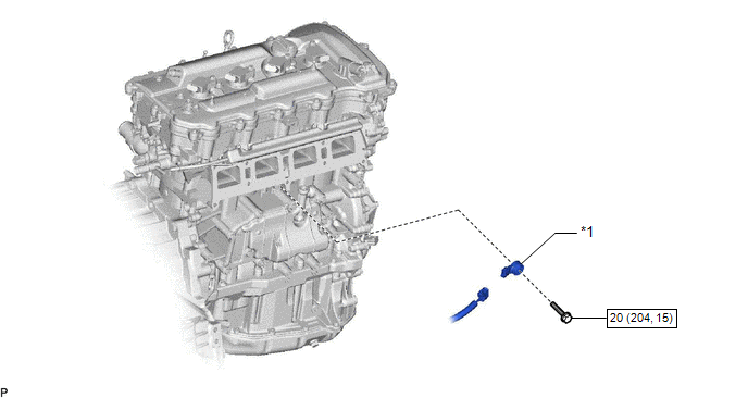
| *1 | KNOCK CONTROL SENSOR | - | - |
.png) | N*m (kgf*cm, ft.*lbf) : Specified torque | - | - |
Removal
REMOVAL
PROCEDURE
1. REMOVE INTAKE MANIFOLD
Click here .gif)
2. REMOVE KNOCK CONTROL SENSOR
| (a) Disconnect the knock control sensor connector. |
|
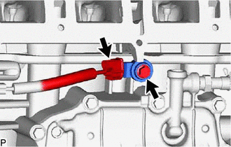
(b) Remove the bolt and knock control sensor.
Inspection
INSPECTION
PROCEDURE
1. INSPECT KNOCK CONTROL SENSOR
(a) Measure the resistance according to the value(s) in the table below.
Standard Resistance:
| Tester Connection | Condition | Specified Condition |
|---|---|---|
| 1 - 2 | 20°C (68°F) | 120 to 280 kΩ |
If the result is not as specified, replace the knock control sensor.
Installation
INSTALLATION
CAUTION / NOTICE / HINT
HINT:
Perform "Inspection After Repairs" after replacing the knock control sensor.
Click here .gif)
PROCEDURE
1. INSTALL KNOCK CONTROL SENSOR
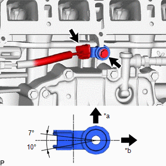
| (a) Install the knock control sensor with the bolt so that the knock control sensor is angled as shown in the illustration. Torque: 20 N·m {204 kgf·cm, 15 ft·lbf} NOTICE:
HINT: Perform "Inspection After Repairs" after replacing the knock control sensor. Click here |
|
(b) Connect the knock control sensor connector.
2. INSTALL INTAKE MANIFOLD
Click here
READ NEXT:
 Manifold Absolute Pressure Sensor
ComponentsCOMPONENTS ILLUSTRATION *1 MANIFOLD ABSOLUTE PRESSURE SENSOR *2 VACUUM HOSE N*m (kgf*cm, ft.*lbf): Specified torque - - On-vehicle InspectionON-VEHICLE INSPECTION P
Mass Air Flow Meter
ComponentsCOMPONENTS ILLUSTRATION *1 MASS AIR FLOW METER SUB-ASSEMBLY - - On-vehicle InspectionON-VEHICLE INSPECTION CAUTION / NOTICE / HINT NOTICE:
Perform the mass air flow meter s
Relay
On-vehicle InspectionON-VEHICLE INSPECTION PROCEDURE 1. INSPECT JUNCTION BLOCK *1 Main Body ECU - - *a Component without harness connected (Junction Block) *b Component without ma
SEE MORE:
Components
COMPONENTS ILLUSTRATION *1 DECK FLOOR BOX LH *2 REAR DECK FLOOR BOX *3 UPPER INSTRUMENT PANEL *4 AUXILIARY BATTERY NEGATIVE TERMINAL N*m (kgf*cm, ft.*lbf): Specified torque - - ILLUSTRATION *1 INSTRUMENT PANEL PASSENGER AIRBAG ASSEMBLY *2 NO. 2 INSTRUMENT
Automatic High Beam
The Automatic High Beam uses an
in-vehicle camera sensor to assess
the brightness of streetlights, the
lights of oncoming and preceding
vehicles, etc., and automatically
turns high beam on or off as necessary.
WARNING
■Limitations of the Automatic High
Beam
Do not rely on the Automatic Hi
