Lexus NX: Terminals Of Ecu
TERMINALS OF ECU
CHECK WINDSHIELD WIPER RELAY ASSEMBLY (w/ Rain Sensor)
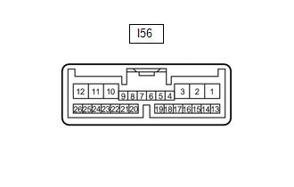
(a) Disconnect the I56 windshield wiper relay assembly connector.
(b) Measure the voltage and resistance according to the value(s) in the table below.
HINT:
Measure the values on the wire harness side with the connector disconnected.
| Terminal No. (Symbol) | Wiring Color | Terminal Description | Condition | Specified Condition |
|---|---|---|---|---|
| I56-2 (IG) - Body ground | L - Body ground | IG power supply | Power switch on (IG) | 11 to 14 V |
| Power switch off | Below 1 V | |||
| I56-8 (VR2) - I56-21 (VR1) | Y - W | Adjusting volume circuit | Windshield wiper switch assembly adjusting ring changed | 0 to 231 Ω |
| I56-12 (E) - Body ground | W-B - Body ground | Body ground | Always | Below 1 Ω |
| I56-16 (WIG) - Body ground | L - Body ground | IG power supply | Power switch on (IG) | 11 to 14 V |
| Power switch off | Below 1 V |
(c) Reconnect the I56 windshield wiper relay assembly connector.
(d) Measure the voltage and waveform according to the value(s) in the table below.
| Terminal No. (Symbol) | Wiring Color | Terminal Description | Condition | Specified Condition |
|---|---|---|---|---|
| I56-1 (+SM) - Body ground | G - Body ground | Front wiper motor operation signal | Front wiper motor in low or high operating | 11 to 14 V |
| Front wiper motor not operating | Below 1 V | |||
| I56-3 (C1) - I56-5 (C0) | GR - L | Front wiper switch AUTO position signal | Power switch on (IG), windshield wiper switch assembly in AUTO position | Below 1 V |
| Power switch on (IG), windshield wiper switch assembly in not AUTO position | 11 to 14 V | |||
| I56-10 (+1) - Body ground | G - Body ground | Front wiper motor low speed signal | Power switch on (IG), front wiper motor in low operating | 11 to 14 V |
| Power switch on (IG), front wiper motor not operating | Below 1 V | |||
| I56-11 (+2) - Body ground | R - Body ground | Front wiper motor high speed signal | Power switch on (IG), front wiper motor in high operating | 11 to 14 V |
| Power switch on (IG), front wiper motor not operating | Below 1 V | |||
| I56-14 (MPX1) - Body ground | V - Body ground | LIN communication signal | Power switch on (IG) | Pulse generation |
| Power switch off | Below 1 V | |||
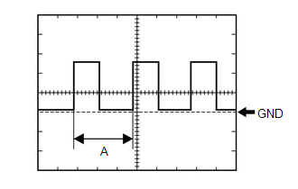
| I56-24 (SPD) - Body ground | B - Body ground | Vehicle speed signal | Driving at approximately 20 km/h (12 mph) | Pulse generation (See waveform 1) |
| I56-25 (W) - Body ground | LA-L - Body ground | Front washer motor signal | Power switch on (IG), front washer switch off | 11 to 14 V |
| Power switch on (IG), front washer switch on | Below 1 V |
(1) Waveform 1 (Reference):
| Item | Condition |
|---|---|
| Tester Connection | I56-24 (SPD) - Body ground |
| Tool Setting | 5 V/DIV., 20 ms/DIV. |
| Vehicle Condition | Driving at approximately 20 km/h (12 mph) |
HINT:
When the system is functioning normally, one wheel revolution generates 4 pulses. As the vehicle speed increases, the width indicated by A in the illustration narrows.
CHECK RAIN SENSOR (w/ Rain Sensor)
(a) Disconnect the T8 rain sensor connector.
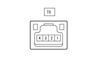
(b) Measure the resistance and voltage according to the value(s) in the table below.
HINT:
Measure the values on the wire harness side with the connector disconnected.
| Terminal No. (Symbol) | Wiring Color | Terminal Description | Condition | Specified Condition |
|---|---|---|---|---|
| T8-4 (SIG) - Body ground | GR - Body ground | IG power supply | Power switch on (IG) | 11 to 14 V |
| Power switch off | Below 1 V | |||
| T8-2 (ES) - Body ground | W - Body ground | Body ground | Always | Below 1 Ω |
(c) Reconnect the T8 rain sensor connector.
(d) Measure the voltage and waveform according to the value(s) in the table below.
| Terminal No. (Symbol) | Wiring Color | Terminal Description | Condition | Specified Condition |
|---|---|---|---|---|
| T8-1 (MPX) - Body ground | V - Body ground | LIN communication signal | Power switch on (IG) | Pulse generation |
| Power switch off | Below 1 V |
CHECK COMBINATION METER ASSEMBLY
(a) Disconnect the I10 combination meter assembly connector.
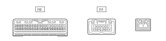
(b) Measure the voltage and resistance according to the value(s) in the table below.
HINT:
Measure the values on the wire harness side with the connector disconnected.
| Terminal No. (Symbol) | Wiring Color | Terminal Description | Condition | Specified Condition |
|---|---|---|---|---|
| I10-22 (B) - Body ground | Y - Body ground | Auxiliary battery power supply | Power switch off | 11 to 14 V |
| I10-21 (IG+) - Body ground | B - Body ground | IG power supply | Power switch on (IG) | 11 to 14 V |
| Power switch off | Below 1 V | |||
| I10-31 (ES) - Body ground | W-B - Body ground | Body ground | Always | Below 1 Ω |
(c) Reconnect the I10 combination meter assembly connector.
(d) Measure the voltage according to the value(s) in the table below.
| Terminal No. (Symbol) | Wiring Color | Terminal Description | Condition | Specified Condition |
|---|---|---|---|---|
| I10-16 (WLVL) - Body ground | LG - Body ground | Washer fluid level signal | Power switch on (IG), washer fluid level not low | 11 to 14 V |
| Power switch on (IG), washer fluid level low | Below 1 V |
(e) Measure the waveform according to the value(s) in the table below.
| Terminal No. (Symbol) | Wiring Color | Terminal Description | Condition | Specified Condition |
|---|---|---|---|---|
| I10-19 (+S) - Body ground | V - Body ground | Speed signal for other system (Output) | Driving at approximately 20 km/h (12 mph) | Pulse generation (See waveform 1) |
(1) Waveform 1 (Reference):
| Item | Condition |
|---|---|
| Tester Connection | I10-19 (+S) - Body ground |
| Tool Setting | 5 V/DIV., 20 ms/DIV. |
| Vehicle Condition | Driving at approximately 20 km/h (12 mph) |
HINT:
When the system is functioning normally, one wheel revolution generates 4 pulses. As the vehicle speed increases, the width indicated by A in the illustration narrows.
HEADLIGHT ECU SUB-ASSEMBLY RH (w/ Headlight Cleaner System, for Triple Beam Headlight)
(a) Disconnect the A20 headlight ECU sub-assembly RH connector.
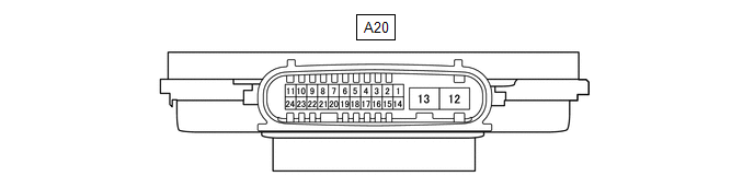
(b) Measure the resistance and voltage according to the value(s) in the table below.
HINT:
Measure the values on the wire harness side with the connector disconnected.
| Terminal No. (Symbol) | Wiring Color | Terminal Description | Condition | Specified Condition |
|---|---|---|---|---|
| A20-4 (IG) - Body ground | G - Body ground | IG power supply | Power switch off | Below 1 V |
| Power switch on (IG) | 11 to 14 V | |||
| A20-12 (GND) - Body ground | W-B - Body ground | Body ground | Always | Below 1 Ω |
(c) Reconnect the A20 headlight ECU sub-assembly RH connector.
(d) Measure the voltage according to the value(s) in the table below.
| Terminal No. (Symbol) | Wiring Color | Terminal Description | Condition | Specified Condition |
|---|---|---|---|---|
| A20-7 (HLC) - Body ground | R - Body ground | Headlight cleaner motor operation signal | Headlight cleaner motor not operating | 11 to 14 V |
| Headlight cleaner motor operating | Below 1 V | |||
| A20-18 (FRWA) - Body ground | B - Body ground | Front washer switch signal | Power switch on (IG), front washer switch on | 11 to 14 V |
| Power switch on (IG), front washer switch off | Below 1 V |
CHECK HEADLIGHT CLEANER CONTROL RELAY (w/ Headlight Cleaner System, for Single Beam Headlight)
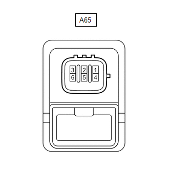
(a) Disconnect the A65 headlight cleaner control relay connector.
(b) Measure the voltage and resistance according to the value(s) in the table below.
HINT:
Measure the values on the wire harness side with the connector disconnected.
| Terminal No. (Symbol) | Wiring Color | Terminal Description | Condition | Specified Condition |
|---|---|---|---|---|
| A65-1 (HDLO) - Body ground | LG - Body ground | Low beam headlight operation signal | Low beam headlights not operating | 11 to 14 V |
| Low beam headlights operating | Below 1 V | |||
| A65-3 (IG) - A65-4 (E) | B - W-B | IG power supply | Power switch on (IG) | 11 to 14 V |
| Power switch off | Below 1 V | |||
| A65-4 (E) - Body ground | W-B - Body ground | Body ground | Always | Below 1 Ω |
(c) Reconnect the A65 headlight cleaner control relay connector.
(d) Measure the voltage according to the value(s) in the table below.
| Terminal No. (Symbol) | Wiring Color | Terminal Description | Condition | Specified Condition |
|---|---|---|---|---|
| A65-5 (FRWA) - A65-4 (E) | W - W-B | Front washer switch signal | Power switch on (IG), front washer switch on | 11 to 14 V |
| Power switch on (IG), front washer switch off | Below 1 V | |||
| A65-6 (+B) - A65-4 (E) | L - W-B | Headlight cleaner motor operation signal | Headlight cleaner motor not operating | 11 to 14 V |
| Headlight cleaner motor operating | Below 1 V |
CHECK MAIN BODY ECU (MULTIPLEX NETWORK BODY ECU) AND INSTRUMENT PANEL JUNCTION BLOCK ASSEMBLY
.png)
| *1 | Main Body ECU (Multiplex Network Body ECU) | - | - |
(a) Remove the main body ECU (multiplex network body ECU) from the instrument panel junction block assembly.
Click here .gif)
(b) Measure the voltage and resistance according to the value(s) in the table below.
| Tester Connection | Wiring Color | Terminal Description | Condition | Specified Condition |
|---|---|---|---|---|
| A-11 (GND1) - Body ground | None - Body ground | Body ground | Always | Below 1 Ω |
| A-31 (BECU) - Body ground | None - Body ground | Auxiliary battery power supply | Power switch off | 11 to 14 V |
| A-30 (ACC) - Body ground | None - Body ground | ACC power supply | Power switch on (ACC) | 11 to 14 V |
| Power switch off | Below 1 V | |||
| A-32 (IG) - Body ground | None - Body ground | IG power supply | Power switch on (IG) | 11 to 14 V |
| Power switch off | Below 1 V |
(c) Install the main body ECU (multiplex network body ECU) to the instrument panel junction block assembly.
Click here
(d) Measure the voltage according to the value(s) in the table below.
| Tester Connection | Wiring Color | Terminal Description | Condition | Specified Condition |
|---|---|---|---|---|
| 4B-53 (HRLY) - Body ground | L - Body ground | Low beam headlight signal | Light control switch in head position | Below 1 V |
| Light control switch off | 11 to 14 V |
READ NEXT:
 Fail-safe Chart
FAIL-SAFE CHART FAIL-SAFE FUNCTION (w/ Rain Sensor) (a) When the windshield wiper switch assembly is in the AUTO position and any of the following conditions are met, intermittent operation according
Data List / Active Test
DATA LIST / ACTIVE TEST DATA LIST HINT: Using the Techstream to read the Data List allows the values or states of switches, sensors, actuators and other items to be read without removing any parts. Th
Headlight Cleaner Motor and Relay Circuit
DESCRIPTION The headlight ECU sub-assembly RH controls the headlight cleaner motor and pump assembly. WIRING DIAGRAM CAUTION / NOTICE / HINT NOTICE:
First check that the front washer operates norm
SEE MORE:
Switch Lights of Remote Touch Always Illuminate or cannot be Controlled Using Rheostat
DESCRIPTION Power is supplied to the remote touch illumination when the light control switch is in the tail or head position. HINT:
When the remote touch is in self check mode, the switch illumination on the remote touch may remain on.
If any illumination controlled by the rheostat switch has a
System Description
SYSTEM DESCRIPTION OUTLINE OF COMBINATION METER ASSEMBLY *a Indication Example *b Hybrid System Indicator or Tachometer *c Speedometer *d
Power Condition
ODO/TRIP Meter
*e Engine Coolant Temperature Receiver Gauge *f Fuel Receiver Gauge *g Multi-informatio
