Lexus NX: Headlight Cleaner Motor and Relay Circuit
DESCRIPTION
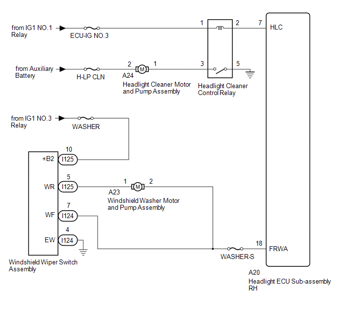
The headlight ECU sub-assembly RH controls the headlight cleaner motor and pump assembly.
WIRING DIAGRAM
CAUTION / NOTICE / HINT
NOTICE:
- First check that the front washer operates normally.
- Inspect the fuses for circuits related to this system before performing the following inspection procedure.
PROCEDURE
| 1. | READ VALUE USING TECHSTREAM |
(a) Read the Data List according to the display on the Techstream.
Click here .gif)
| Tester Display | Measurement Item | Range | Normal Condition | Diagnostic Note |
|---|---|---|---|---|
| Front Window Washer Switch | Washer switch condition | ON/OFF | ON: Windshield wiper switch assembly (front washer switch) on OFF: Windshield wiper switch assembly (front washer switch) off | - |
| Tester Display |
|---|
| Front Window Washer Switch |
OK:
On the Techstream screen, ON or OFF is displayed accordingly.
| NG | .gif) | GO TO STEP 7 |
|
.gif)
| 2. | INSPECT HEADLIGHT CLEANER CONTROL RELAY |
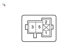
(a) Remove the headlight cleaner control relay from the No. 2 engine room relay block.
(b) Inspect the headlight cleaner control relay.
Click here
| NG | | REPLACE HEADLIGHT CLEANER CONTROL RELAY |
|
| 3. | CHECK HARNESS AND CONNECTOR (HEADLIGHT CLEANER CONTROL RELAY - BATTERY) |
| (a) Remove the headlight cleaner control relay from the No. 2 engine room relay block. |
|
(b) Measure the voltage according to the value(s) in the table below.
Standard Voltage:
| Tester Connection | Switch Condition | Specified Condition |
|---|---|---|
| Headlight cleaner control relay terminal 1 - Body ground | Power switch on (IG) | 11 to 14 V |
| NG | | REPAIR OR REPLACE HARNESS OR CONNECTOR |
|
| 4. | CHECK HEADLIGHT CLEANER MOTOR AND PUMP ASSEMBLY CIRCUIT |
| (a) Remove the headlight cleaner control relay from the No. 2 engine room relay block. |
|
(b) Using a service wire, connect terminal 3 and body ground.
NOTICE:
Do not forcibly insert the service wire into the terminals of the connector when connecting a service wire.
(c) Check the headlight cleaner motor and pump assembly operate.
OK:
Headlight cleaner motor and pump assembly operate.
| NG | | GO TO STEP 8 |
|
| 5. | CHECK HARNESS AND CONNECTOR (HEADLIGHT CLEANER CONTROL RELAY - BODY GROUND) |
| (a) Remove the headlight cleaner control relay from the No. 2 engine room relay block. |
|
(b) Measure the resistance according to the value(s) in the table below.
Standard Resistance:
| Tester Connection | Condition | Specified Condition |
|---|---|---|
| Headlight cleaner control relay terminal 5 - Body ground | Always | Below 1 Ω |
| NG | | REPAIR OR REPLACE HARNESS OR CONNECTOR |
|
| 6. | CHECK HARNESS AND CONNECTOR (HEADLIGHT CLEANER CONTROL RELAY - HEADLIGHT ECU SUB-ASSEMBLY RH) |
(a) Remove the headlight cleaner control relay from the No. 2 engine room relay block.
(b) Disconnect the A20 headlight ECU sub-assembly RH connector.
(c) Measure the resistance according to the value(s) in the table below.
Standard Resistance:
| Tester Connection | Condition | Specified Condition |
|---|---|---|
| Headlight cleaner control relay terminal 2 - A20-7 (HLC) | Always | Below 1 Ω |
| Headlight cleaner control relay terminal 2 or A20-7 (HLC) - Body ground | Always | 10 kΩ or higher |
| OK | | REPLACE HEADLIGHT ECU SUB-ASSEMBLY RH |
| NG | | REPAIR OR REPLACE HARNESS OR CONNECTOR |
| 7. | CHECK HARNESS AND CONNECTOR (HEADLIGHT ECU SUB-ASSEMBLY RH - WINDSHIELD WIPER SWITCH ASSEMBLY) |
(a) Disconnect the A20 headlight ECU sub-assembly RH connector.
(b) Disconnect the I124 windshield wiper switch assembly connector.
(c) Measure the resistance according to the value(s) in the table below.
Standard Resistance:
| Tester Connection | Condition | Specified Condition |
|---|---|---|
| A20-18 (FRWA) - I124-7 (WF) | Always | Below 1 Ω |
| A20-18 (FRWA) or I124-7 (WF) - Body ground | Always | 10 kΩ or higher |
| OK | | REPLACE HEADLIGHT ECU SUB-ASSEMBLY RH |
| NG | | REPAIR OR REPLACE HARNESS OR CONNECTOR |
| 8. | CHECK HARNESS AND CONNECTOR (HEADLIGHT CLEANER MOTOR AND PUMP ASSEMBLY - BATTERY) |
| (a) Disconnect the headlight cleaner motor and pump assembly connector. |
|
(b) Measure the voltage according to the value(s) in the table below.
Standard Voltage:
| Tester Connection | Switch Condition | Specified Condition |
|---|---|---|
| A24-2 - Body ground | Power switch off | 11 to 14 V |
| NG | | REPAIR OR REPLACE HARNESS OR CONNECTOR |
|
| 9. | INSPECT HEADLIGHT CLEANER MOTOR AND PUMP ASSEMBLY |
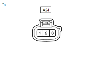
(a) Disconnect the A24 headlight cleaner motor and pump assembly connector.
(b) Inspect the headlight cleaner motor and pump assembly.
Click here
| NG | | REPLACE HEADLIGHT CLEANER MOTOR AND PUMP ASSEMBLY |
|
| 10. | CHECK HARNESS AND CONNECTOR (HEADLIGHT CLEANER MOTOR AND PUMP ASSEMBLY - HEADLIGHT CLEANER CONTROL RELAY) |
(a) Disconnect the A24 headlight cleaner motor and pump assembly connector.
(b) Remove the headlight cleaner control relay from the No. 2 engine room relay block.
(c) Measure the resistance according to the value(s) in the table below.
Standard Resistance:
| Tester Connection | Condition | Specified Condition |
|---|---|---|
| A24-1 - Headlight cleaner control relay terminal 3 | Always | Below 1 Ω |
| A24-1 or headlight cleaner control relay terminal 3 - Body ground | Always | 10 kΩ or higher |
| OK | | USE SIMULATION METHOD TO CHECK |
| NG | | REPAIR OR REPLACE HARNESS OR CONNECTOR |
READ NEXT:
 Washer Fluid Level Warning Switch Circuit
DESCRIPTION When the volume of washer fluid decreases to below a certain level (when the level warning switch assembly is turned on), the multi-information display warns the driver by displaying a mes
Components
COMPONENTS ILLUSTRATION *1 DECK FLOOR BOX LH *2 NO. 3 DECK BOARD SUB-ASSEMBLY *3 REAR DECK FLOOR BOX *4 NEGATIVE AUXILIARY BATTERY TERMINAL N*m (kgf*cm, ft.*lbf): Specified
SEE MORE:
Open in One Side of Bus 3 Branch Line
DESCRIPTION When the CAN bus main lines are normal (no open, short to ground, short to +B or short between lines) and there is an ECU or sensor on the "Communication Bus Check" screen that is indicated as not communicating or whose connection status on the "Communication Bus Check" screen changes in
Adjustment
ADJUSTMENT PROCEDURE 1. INSPECT SHIFT LEVER POSITION SENSOR POSITION (a) Apply the parking brake. (b) Lock the wheels with chocks to secure the vehicle. (c) Turn the power switch on (READY). (d) Move the shift lever to D and release the brake. NOTICE: Be sure to apply the parking brake and lock the
