- Shift Sensor Shift Pos
- Shift Sensor SW - P
- Shift Sensor SW - R
- Shift Sensor SW - PR
- Shift Sensor SW - N
- Shift Sensor SW - DB1
- Shift Sensor SW - DB2
- Shift Sensor SW - PNB
Lexus NX: Transmission Range Sensor Circuit (P0705-757)
Lexus NX Service Manual / Engine & Hybrid System / 2ar-fxe (hybrid / Battery Control) / Hybrid Control System / Transmission Range Sensor Circuit (P0705-757)
DESCRIPTION
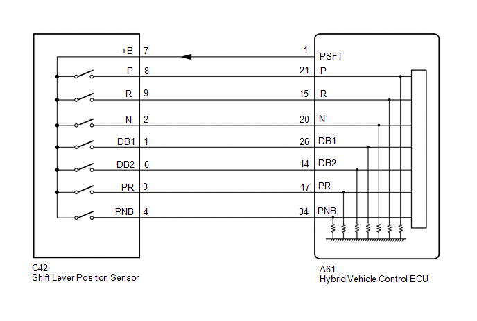
The shift lever position sensor sends 7 different switch signals to the hybrid vehicle control ECU. The hybrid vehicle control ECU uses these signals to detect the shift lever position (P, R, N, D or S). The hybrid vehicle control ECU also uses this information to determine the intended direction of travel (forward or reverse).
| DTC No. | Detection Item | DTC Detection Condition | Trouble Area | MIL | Warning Indicate |
|---|---|---|---|---|---|
| P0705-757 | Transmission Range Sensor Circuit | Shift sensor circuit malfunction (abnormal pattern) A malfunction in the P, R, N, D or S circuit is detected based on the shift sensor input pattern. (1 trip detection logic) |
| Does not come on | Master Warning Light: Comes on |
| DTC No. | ECU Data List |
|---|---|
| P0705-757 | |
WIRING DIAGRAM
CAUTION / NOTICE / HINT
HINT:
After the repair, clear the DTCs and perform the following procedure to check that DTCs are not output.
- Turn the power switch on (IG).
- Slowly move the shift lever from P to S then back to P.
PROCEDURE
| 1. | READ VALUE USING TECHSTREAM (SHIFT SENSOR SW) |
(a) Connect the Techstream the DLC3.
(b) Turn the power switch on (IG).
(c) Enter the following menus: Powertrain / Hybrid Control / Data List / Shift Sensor SW - P, Shift Sensor SW - R, Shift Sensor SW - PR, Shift Sensor SW - N, Shift Sensor SW - DB1, Shift Sensor SW - DB2, Shift Sensor SW - PNB.
Powertrain > Hybrid Control > Data List| Tester Display |
|---|
| Shift Sensor SW - P |
| Shift Sensor SW - R |
| Shift Sensor SW - PR |
| Shift Sensor SW - N |
| Shift Sensor SW - DB1 |
| Shift Sensor SW - DB2 |
| Shift Sensor SW - PNB |
(d) While slowly moving the shift lever from P to S, then back to P, read the Data List (Shift Sensor SW) displayed on the Techstream.
HINT:
Be sure to move the shift lever slowly.
| ECU Data List | Shift Position | ||||
| P | R | N | D | S | |
| Shift Sensor SW-P | ON | OFF | OFF | OFF | OFF |
| Shift Sensor SW-R | OFF | ON | OFF | OFF | OFF |
| Shift Sensor SW-PR | ON | ON | OFF | OFF | OFF |
| Shift Sensor SW-N | OFF | OFF | ON | OFF | OFF |
| Shift Sensor SW-DB1 | OFF | OFF | OFF | ON | ON |
| Shift Sensor SW-DB2 | OFF | OFF | OFF | ON | ON |
| Shift Sensor SW-PNB | ON | OFF | ON | OFF | ON |
(e) Check for DTCs.
OK:
DTC P0705-757 is not output.
(f) Turn the power switch off.
| NG | .gif) | GO TO STEP 3 |
|
.gif)
| 2. | CHECK FOR INTERMITTENT PROBLEMS |
Click here .gif)
| OK | | REPLACE HYBRID VEHICLE CONTROL ECU |
| NG | | REPAIR OR REPLACE MALFUNCTIONING PARTS, COMPONENT AND AREA |
| 3. | CHECK SHIFT LEVER POSITION SENSOR |
(a) Turn the power switch on (IG).
| (b) Measure the voltage according to the value(s) in the table below. Standard Voltage:
|
|
(c) Turn the power switch off.
| OK | | REPLACE HYBRID VEHICLE CONTROL ECU |
|
| 4. | CHECK HARNESS AND CONNECTOR (POWER SOURCE CIRCUIT) |
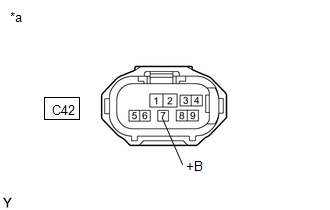
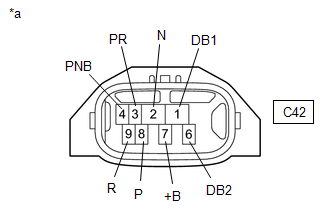
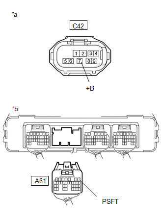
(a) Disconnect the C42 shift lever position sensor connector.
Click here
(b) Turn the power switch on (IG).
| (c) Measure the voltage according to the value(s) in the table below. Standard Voltage:
NOTICE: Turning the power switch on (IG) with the shift lever position sensor connector disconnected causes other DTCs to be stored. Clear the DTCs after performing this inspection. |
|
(d) Turn the power switch off.
(e) Reconnect the C42 shift lever position sensor connector.
| NG | | GO TO STEP 6 |
|
| 5. | INSPECT SHIFT LEVER POSITION SENSOR |
(a) Disconnect the C42 shift lever position sensor connector.
| (b) Measure the resistance according to the value(s) in the table below. Standard Resistance:
|
|
(c) Reconnect the C42 shift lever position sensor connector.
| OK | | REPAIR OR REPLACE HARNESS OR CONNECTOR |
| NG | | REPLACE SHIFT LEVER POSITION SENSOR |
| 6. | CHECK HARNESS AND CONNECTOR (SHIFT LEVER POSITION SENSOR - HYBRID VEHICLE CONTROL ECU) |
(a) Disconnect the C42 shift lever position sensor connector.
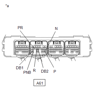
(b) Disconnect the A61 hybrid vehicle control ECU connector.
| (c) Measure the resistance according to the value(s) in the table below. Standard Resistance:
|
|
(d) Reconnect the A61 hybrid vehicle control ECU connector.
(e) Reconnect the C42 shift lever position sensor connector.
| OK | | REPAIR OR REPLACE POWER SOURCE CIRCUIT |
| NG | | REPAIR OR REPLACE HARNESS OR CONNECTOR |
READ NEXT:
 Motor Electronics Coolant Temperature Sensor Circuit Range / Performance (P0A01-726,P0A04-725)
DTC SUMMARY MALFUNCTION DESCRIPTION These DTCs indicate the temperature sensor value is abnormal. The cause of this malfunction may be one of the following: Area Main Malfunction Description St
Motor Electronics Coolant Temperature Sensor Circuit Low (P0A02-719,P0A03-720)
DESCRIPTION Refer to the description for DTC P0A01-726. Click here DTC No. Detection Item DTC Detection Condition Trouble Area MIL Warning Indicate P0A02-719 Motor Electronics Coo
DC / DC Converter Status Circuit (P0A08-264)
DESCRIPTION The DC/DC converter converts the DC 244.8 V of the HV battery into DC 12 V in order to supply power to areas such as the vehicle's lighting, audio, and ECU systems. In addition, it charges
SEE MORE:
Installation
INSTALLATION CAUTION / NOTICE / HINT NOTICE:
Handle components indoors as much as possible to prevent foreign matter from entering and adhering to headlight assembly components.
Do not reuse parts which have reduced fastening ability due to thread damage.
When installing components, make sure
Radio Broadcast cannot be Received or Poor Reception
WIRING DIAGRAM CAUTION / NOTICE / HINT NOTICE: When replacing the radio receiver assembly, always replace it with a new one. If a radio receiver assembly which was installed to another vehicle is used, the following may occur:
A communication malfunction DTC may be stored.
The radio receiver a
© 2016-2026 Copyright www.lexunx.com
