Lexus NX: Turn Signal Switch Circuit
DESCRIPTION
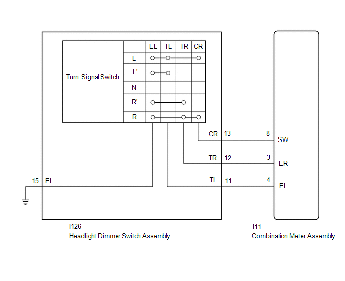
The combination meter receives the turn signal switch information and controls the turn signal lights.
WIRING DIAGRAM
CAUTION / NOTICE / HINT
NOTICE:
When replacing the combination meter assembly, make sure to replace it with a new one.
PROCEDURE
| 1. | READ VALUE USING TECHSTREAM (TURN SIGNAL SWITCH) |
(a) Using the Techstream, read the Data List.
Click here .gif)
| Tester Display | Measurement Item | Range | Normal Condition | Diagnostic Note |
|---|---|---|---|---|
| Turn Signal Switch (Right) | Turn signal switch (right) signal | ON or OFF | ON: Turn signal switch (right) on OFF: Turn signal switch (right) off | - |
| Turn Signal Switch (Left) | Turn signal switch (left) signal | ON or OFF | ON: Turn signal switch (left) on OFF: Turn signal switch (left) off | - |
| Tester Display |
|---|
| Turn Signal Switch (Right) |
| Turn Signal Switch (Left) |
| Result | Proceed to |
|---|---|
| Data List values are as specified | A |
| Data List values are not as specified | B |
| A | .gif) | PROCEED TO NEXT SUSPECTED AREA SHOWN IN PROBLEM SYMPTOMS TABLE |
|
.gif)
| 2. | INSPECT HEADLIGHT DIMMER SWITCH ASSEMBLY (TURN SIGNAL SWITCH) |
(a) Remove the headlight dimmer switch assembly.
Click here
(b) Inspect the headlight dimmer switch assembly.
Click here
| NG | | REPLACE HEADLIGHT DIMMER SWITCH ASSEMBLY |
|
| 3. | CHECK HARNESS AND CONNECTOR (HEADLIGHT DIMMER SWITCH ASSEMBLY - COMBINATION METER ASSEMBLY AND BODY GROUND) |
(a) Disconnect the I126 headlight dimmer switch assembly connector.
(b) Disconnect the I11 combination meter assembly connector.
(c) Measure the resistance according to the value(s) in the table below.
Standard Resistance:
| Tester Connection | Condition | Specified Condition |
|---|---|---|
| I126-11 (TL) - I11-4 (EL) | Always | Below 1 Ω |
| I126-12 (TR) - I11-3 (ER) | ||
| I126-13 (CR) - I11-8 (SW) | ||
| I126-15 (EL) - Body ground | ||
| I126-11 (TL) - Body ground | Always | 10 kΩ or higher |
| I126-12 (TR) - Body ground | ||
| I26-13 (CR) - Body ground |
| OK | | REPLACE COMBINATION METER ASSEMBLY |
| NG | | REPAIR OR REPLACE HARNESS OR CONNECTOR |
READ NEXT:
 Headlight Dimmer Switch Circuit
DESCRIPTION The main body ECU (multiplex network body ECU) receives light control switch signals, dimmer switch signals, fog light switch signals from the headlight dimmer switch. WIRING DIAGRAM CAUT
Daytime Running Light Relay Circuit
DESCRIPTION The illumination of the daytime running light (clearance light assembly) or clearance light is controlled by the headlight light control ECU sub-assembly. WIRING DIAGRAM CAUTION / NOTICE
Front Fog Light Circuit
DESCRIPTION Illumination of the front fog lights is controlled by the main body ECU (multiplex network body ECU). WIRING DIAGRAM CAUTION / NOTICE / HINT NOTICE:
Inspect the fuses for circuits rela
SEE MORE:
Invalid Data Received from Hybrid Powertrain Control Module Invalid Serial Data Received (U059481)
DESCRIPTION If the hybrid vehicle control ECU cannot recognize the forward recognition camera. DTC U059481 is stored. DTC No. Detection Item DTC Detection Condition Trouble Area DTC Output from U059481 Invalid Data Received from Hybrid Powertrain Control Module Invalid Serial Data R
Steering Angle Sensor Failure (C1626)
DESCRIPTION This DTC is stored if the clearance warning ECU assembly receives a signal via CAN communication from the steering sensor that indicates an internal malfunction. DTC No. Detection Item DTC Detection Condition Trouble Area C1626 Steering Angle Sensor Failure A fail flag i
