- Power switch off
- Electrical key transmitter sub-assembly brought outside detection area but kept inside wireless function operational area
- Lock or unlock switch of electrical key transmitter sub-assembly not pressed → pressed
Lexus NX: Wireless Door Lock Tuner Circuit Malfunction (B1242)
Lexus NX Service Manual / Vehicle Interior / Door Lock / Wireless Door Lock Control System / Wireless Door Lock Tuner Circuit Malfunction (B1242)
DESCRIPTION
The door control receiver is used to receive radio waves related to the entry functions of the electrical key transmitter sub-assembly. The certification ECU (smart key ECU assembly) decodes the requested electrical key transmitter sub-assembly operation by identifying a key code based on the radio waves received via the door control receiver. The door control receiver receives a signal from the electrical key transmitter sub-assembly and sends signals to the main body ECU (multiplex network body ECU) through the certification ECU (smart key ECU assembly). (ex. if a door lock operation is requested, the certification ECU [smart key ECU assembly] sends a door lock command to the main body ECU [multiplex network body ECU]).
| DTC No. | Detection Item | DTC Detection Condition | Trouble Area |
|---|---|---|---|
| B1242 | Wireless Door Lock Tuner Circuit Malfunction |
|
|
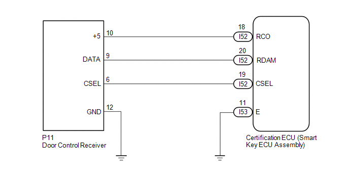
WIRING DIAGRAM
CAUTION / NOTICE / HINT
NOTICE:
- When replacing or inspecting the door control receiver and wire harness, do not change the position or length of the wire harness. If the wire harness is too close to the door control receiver, entry and wireless function performance may be affected.
- This DTC is not stored within 10 seconds of the power switch being turned from on (IG) to off.
-
The wireless door lock control system uses the CAN communication system. Inspect the communication function by following How to Proceed with Troubleshooting. Troubleshoot the wireless door lock control system after confirming that the communication system is functioning properly.
Click here
.gif)
-
When replacing the door control receiver, read the transmitter IDs (tire pressure warning system) stored in the old ECU using the Techstream and write them down before removal.
Click here
-
It is necessary to perform initialization ( ) after registration ( ) of the transmitter IDs into the door control receiver if the door control receiver has been replaced.
-
If the certification ECU (smart key ECU assembly) is replaced, refer to the Smart Access System with Push-button Start (for Entry Function).
Click here
PROCEDURE
| 1. | CHECK CERTIFICATION ECU (SMART KEY ECU ASSEMBLY) |
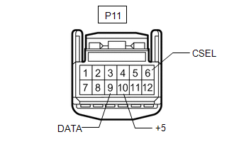
| (a) Disconnect the door control receiver connector. |
|
(b) Check for pulses and voltage according to the value(s) in the table below.
Standard Voltage:
| Tester Connection | Condition | Specified Condition |
|---|---|---|
| P11-10 (+5) - Body ground | Procedure: | Pulse generation |
| P11-6 (CSEL) - Body ground | Procedure:
| Below 1 V → Pulse generation |
| P11-9 (DATA) - Body ground | Procedure:
| Pulse generation |
| NG | .gif) | REPLACE DOOR CONTROL RECEIVER |
|
.gif)
| 2. | CHECK HARNESS AND CONNECTOR (DOOR CONTROL RECEIVER - CERTIFICATION ECU [SMART KEY ECU ASSEMBLY] AND BODY GROUND) |
(a) Disconnect the I52 and I53 certification ECU (smart key ECU assembly) connectors.
(b) Disconnect the P11 door control receiver connector.
(c) Measure the resistance according to the value(s) in the table below.
Standard Resistance:
| Tester Connection | Condition | Specified Condition |
|---|---|---|
| I52-19 (CSEL) - P11-6 (CSEL) | Always | Below 1 Ω |
| I52-20 (RDAM) - P11-9 (DATA) | Always | Below 1 Ω |
| I52-18 (RCO) - P11-10 (+5) | Always | Below 1 Ω |
| I53-11 (E) - Body ground | Always | Below 1 Ω |
| P11-12 (GND) - Body ground | Always | Below 1 Ω |
| I52-19 (CSEL) or P11-6 (CSEL) - Body ground | Always | 10 kΩ or higher |
| I52-20 (RDAM) or P11-9 (DATA) - Body ground | Always | 10 kΩ or higher |
| I52-18 (RCO) or P11-10 (+5) - Body ground | Always | 10 kΩ or higher |
| OK | | REPLACE CERTIFICATION ECU (SMART KEY ECU ASSEMBLY) |
| NG | | REPAIR OR REPLACE HARNESS OR CONNECTOR |
READ NEXT:
 No Answer-Back
DESCRIPTION In some cases, wireless door lock control functions are normal but the hazard warning light and/or wireless door lock buzzer answer-back function does not operate. In such cases, hazard wa
Air Conditioning Amplifier
ComponentsCOMPONENTS ILLUSTRATION *1 AIR CONDITIONING AMPLIFIER ASSEMBLY *2 INNER NO. 1 INSTRUMENT PANEL BRACE COVER RH RemovalREMOVAL PROCEDURE 1. REMOVE INNER NO. 1 INSTRUMENT PANEL B
SEE MORE:
Parts Location
PARTS LOCATION ILLUSTRATION *1 NO. 1 ENGINE ROOM RELAY BLOCK
EPB NO. 1 FUSE
EPB NO. 2 FUSE
HINT: EPB stands for Electric Parking Brake. *2 NO. 2 ENGINE ROOM RELAY BLOCK
ECU-B NO. 1 FUSE
ECU-B NO. 2 FUSE
*3 SKID CONTROL ECU (BRAKE BOOSTER WITH MASTER CYLINDER ASSEMBLY)
Components
COMPONENTS ILLUSTRATION *1 OUTSIDE MOULDING RETAINER *2 REAR DOOR LOWER OUTSIDE MOULDING SUB-ASSEMBLY LH *3 REAR DOOR NO. 2 WEATHERSTRIP LH *4 REAR DOOR REAR UPPER OUTSIDE MOULDING LH *5 HOLE COVER - - ● Non-reusable part - - ILLUSTRATION *1 REAR DO
© 2016-2026 Copyright www.lexunx.com
