Lexus NX: Adjustment
ADJUSTMENT
CAUTION / NOTICE / HINT
HINT:
- Centering bolts are used to mount the hood hinge to the vehicle body and hood. The hood cannot be adjusted with the centering bolts on. Substitute the centering bolts for standard bolts (with washers) when making adjustments.
-
A bolt without a torque specification is shown in the standard bolt chart.
Click here
.gif)
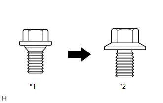
| *1 | Centering Bolt |
| *2 | Standard Bolt |
PROCEDURE
1. INSPECT HOOD SUB-ASSEMBLY
Click here
2. REMOVE RADIATOR SUPPORT OPENING COVER
Click here
3. ADJUST HOOD SUB-ASSEMBLY
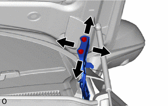
| (a) Adjust the hood position. (1) Loosen the 4 hinge bolts on the hood and adjust the hood position. (2) Move the hood and adjust the clearance between the hood and front fender. (3) Tighten the 4 hinge bolts on the hood after the adjustment. Torque: 13 N·m {133 kgf·cm, 9.6 ft·lbf} |
|
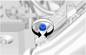
| (b) Adjust the cushion rubber so that the hood and fender are aligned. HINT: Raise or lower the front end of the hood by turning the cushion rubber. |
|
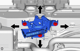
| (c) Adjust the hood lock. (1) Loosen the 3 bolts. (2) Adjust the hood lock position so that the striker can enter it smoothly. (3) Tighten the 3 bolts after the adjustment. Torque: 8.0 N·m {82 kgf·cm, 71 in·lbf} |
|
4. INSTALL RADIATOR SUPPORT OPENING COVER
Click here
READ NEXT:
 Reassembly
REASSEMBLY PROCEDURE 1. INSTALL ENGINE HOOD LOCK STRIKER ASSEMBLY (a) Attach the guide. (b) Install the engine hood lock striker assembly with the 2 bolts. Torque: 8.0 N·m {82 kgf·cm, 71 in·lbf} 2
Components
COMPONENTS ILLUSTRATION *1 CENTER HOOD CUSHION *2 HOOD LOCK ASSEMBLY *3 HOOD LOCK CONTROL CABLE ASSEMBLY *4 HOOD TO FRONT FENDER SEAL LH *5 RADIATOR SUPPORT OPENING COVER -
SEE MORE:
Components
COMPONENTS ILLUSTRATION *1 DECK FLOOR BOX LH *2 NO. 3 DECK BOARD SUB-ASSEMBLY *3 REAR DECK FLOOR BOX *4 AUXILIARY BATTERY NEGATIVE TERMINAL N*m (kgf*cm, ft.*lbf): Specified torque - - ILLUSTRATION *1 AIRBAG ECU ASSEMBLY *2 FRONT CONSOLE BOX N*m (kgf
Components
COMPONENTS ILLUSTRATION *1 DECK FLOOR BOX LH *2 NO. 3 DECK BOARD SUB-ASSEMBLY *3 REAR DECK FLOOR BOX *4 NEGATIVE AUXILIARY BATTERY TERMINAL N*m (kgf*cm, ft.*lbf): Specified torque - - ILLUSTRATION *A for 8 Inch Display *B for 10.3 Inch Display *1 CEN
