Lexus NX: Components
COMPONENTS
ILLUSTRATION
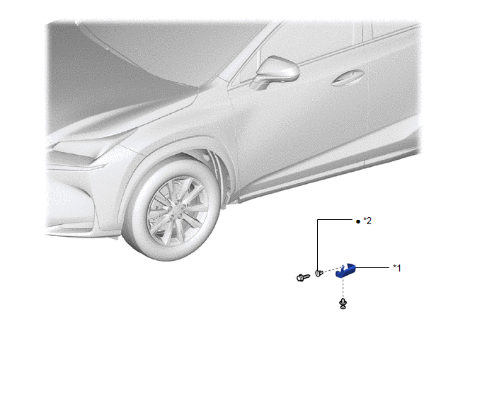
| *1 | SIDE MUDGUARD SUB-ASSEMBLY LH | *2 | GROMMET |
| ● | Non-reusable part | - | - |
ILLUSTRATION
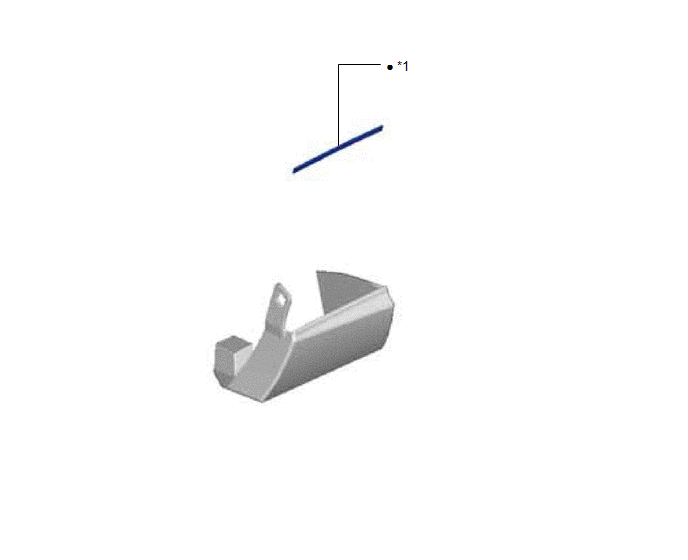
| *1 | NO. 3 MOULDING TAPE | - | - |
| ● | Non-reusable part | - | - |
READ NEXT:
 Removal
REMOVAL CAUTION / NOTICE / HINT HINT:
Use the same procedure for the RH and LH sides.
The procedure listed below is for the LH side.
PROCEDURE 1. REMOVE SIDE MUDGUARD SUB-ASSEMBLY LH HINT: Whe
Disassembly
DISASSEMBLY CAUTION / NOTICE / HINT HINT:
Use the same procedure for the RH and LH sides.
The procedure listed below is for the LH side.
PROCEDURE 1. REMOVE NO. 3 MOULDING TAPE (a) Remove the
Reassembly
REASSEMBLY CAUTION / NOTICE / HINT HINT:
Use the same procedure for the RH and LH sides.
The procedure listed below is for the LH side.
PROCEDURE 1. INSTALL NO. 3 MOULDING TAPE (a) Clean the N
SEE MORE:
System Diagram
SYSTEM DIAGRAM CERTIFICATION ECU (SMART KEY ECU ASSEMBLY) Component Function Front door outside handle assembly Receives request signals from the certification ECU (smart key ECU assembly) via the built-in electrical key antenna (front door) and forms the vehicle exterior detection area
Components
COMPONENTS ILLUSTRATION *A w/o Power Back Door System *B w/ Power Back Door System *1 BACK DOOR FINISH COVER LH *2 BACK DOOR FINISH COVER RH *3 BACK DOOR LOCK COVER *4 BACK DOOR OUTSIDE GARNISH SUB-ASSEMBLY *5 BACK DOOR SIDE GARNISH LH *6 BACK DOOR SIDE GARNIS
© 2016-2026 Copyright www.lexunx.com
