Lexus NX: Cooling Fan Circuit
DESCRIPTION
The ECM calculates an appropriate cooling fan speed based on the engine coolant temperature, air conditioning switch condition, refrigerant pressure, hybrid coolant temperature, engine speed and vehicle speed, and sends the signals to the cooling fan ECU to regulate the cooling fans. The cooling fan ECU controls the cooling fan speed based on the duty ratio signal sent from the ECM. By basing its control on the operating conditions, the ECM can control the fan speed optimally using the cooling fan ECU, achieving both high cooling performance and quietness.
WIRING DIAGRAM
Click here .gif)
CAUTION / NOTICE / HINT
NOTICE:
Inspect the fuses for circuits related to this system before performing the following procedure.
PROCEDURE
| 1. | PERFORM ACTIVE TEST USING TECHSTREAM (Control the Electric Cooling Fan) |
(a) Connect the Techstream to the DLC3.
(b) Turn the power switch on (IG).
(c) Turn the Techstream on.
(d) Enter the following menus: Powertrain / Engine and ECT / Active Test / Control the Electric Cooling Fan.
(e) Check the operation of the cooling fans while operating them using the Techstream.
Powertrain > Engine and ECT > Active Test| Tester Display |
|---|
| Control the Electric Cooling Fan |
OK:
| Tester Operation | Fan Operation |
|---|---|
| ON | Cooling fans operate |
| OFF | Cooling fans stop |
| Result | Proceed to |
|---|---|
| OK | A |
| NG (Cooling fans do not operate) | B |
| NG (Cooling fans do not stop) | C |
(f) Turn the power switch off.
| A |  | PROCEED TO NEXT SUSPECTED AREA SHOWN IN PROBLEM SYMPTOMS TABLE |
| C | | GO TO STEP 11 |
|

| 2. | CHECK COOLING FAN SYSTEM |
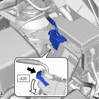
| (a) Disconnect the A35 ECM connector. |
|
(b) Turn the power switch on (IG).
(c) Check the operation of the cooling fans.
OK:
Cooling fans operate.
(d) Turn the power switch off.
(e) Reconnect the A35 ECM connector.
| OK | | REPLACE ECM |
|
| 3. | INSPECT COOLING FAN MOTOR (COOLING FAN MOTOR AND NO. 2 COOLING FAN MOTOR) |
(a) Inspect the cooling fan motor and No. 2 cooling fan motor.
Click here
| Result | Proceed to |
|---|---|
| OK | A |
| NG (Cooling fan motor) | B |
| NG (No. 2 cooling fan motor) | C |
| B | | REPLACE COOLING FAN MOTOR |
| C | | REPLACE NO. 2 COOLING FAN MOTOR |
|
| 4. | CHECK HARNESS AND CONNECTOR (POWER SOURCE CIRCUIT) |
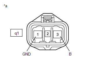
(a) Disconnect the q1 cooling fan ECU connector.
(b) Turn the power switch on (IG).
| (c) Measure the voltage according to the value(s) in the table below. Standard Voltage:
|
|
(d) Turn the power switch off.
(e) Reconnect the q1 cooling fan ECU connector.
| NG | | GO TO STEP 6 |
|
| 5. | CHECK HARNESS AND CONNECTOR (ECM - COOLING FAN ECU) |
(a) Disconnect the A35 ECM connector.
(b) Disconnect the q1 cooling fan ECU connector.
(c) Measure the resistance according to the value(s) in the table below.
Standard Resistance:
| Tester Connection | Condition | Specified Condition |
|---|---|---|
| A35-44 (RFC) or q1-2 (SI) - Body ground | Always | 10 kΩ or higher |
(d) Reconnect the q1 cooling fan ECU connector.
(e) Reconnect the A35 ECM connector.
| OK | | REPLACE COOLING FAN ECU |
| NG | | REPAIR OR REPLACE HARNESS OR CONNECTOR |
| 6. | CHECK HARNESS AND CONNECTOR (COOLING FAN ECU - BODY GROUND) |
(a) Disconnect the q1 cooling fan ECU connector.
(b) Measure the resistance according to the value(s) in the table below.
Standard Resistance:
| Tester Connection | Condition | Specified Condition |
|---|---|---|
| q1-1 (GND) - Body ground | Always | Below 1 Ω |
(c) Reconnect the q1 cooling fan ECU connector.
| NG | | REPAIR OR REPLACE HARNESS OR CONNECTOR |
|
| 7. | INSPECT FAN NO.1 RELAY |
(a) Inspect the FAN NO.1 relay.
Click here
| NG | | REPLACE FAN NO.1 RELAY |
|
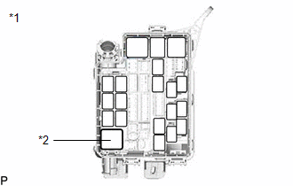
| 8. | INSPECT NO. 2 ENGINE ROOM RELAY BLOCK (FAN NO.1 RELAY) |
(a) Remove the FAN NO.1 relay from the No. 2 engine room relay block.
| (b) Measure the voltage according to the value(s) in the table below. Standard Voltage:
|
|
(c) Reinstall the FAN NO.1 relay.
| NG | | REPAIR OR REPLACE HARNESS OR CONNECTOR |
|
| 9. | CHECK HARNESS AND CONNECTOR (COOLING FAN ECU - FAN NO.1 RELAY) |
(a) Disconnect the q1 cooling fan ECU connector.
(b) Remove the FAN NO.1 relay from the No. 2 engine room relay block.
(c) Measure the resistance according to the value(s) in the table below.
Standard Resistance:
| Tester Connection | Condition | Specified Condition |
|---|---|---|
| q1-3 (B) - 5 (FAN NO.1 relay holder) | Always | Below 1 Ω |
| q1-3 (B) or 5 (FAN NO.1 relay holder) - Body ground | Always | 10 kΩ or higher |
(d) Reinstall the FAN NO.1 relay.
(e) Reconnect the q1 cooling fan ECU connector.
| NG | | REPAIR OR REPLACE HARNESS OR CONNECTOR |
|
| 10. | CHECK HARNESS AND CONNECTOR (FAN NO.1 RELAY - BODY GROUND) |
(a) Remove the FAN NO.1 relay from the No. 2 engine room relay block.
(b) Measure the resistance according to the value(s) in the table below.
Standard Resistance:
| Tester Connection | Condition | Specified Condition |
|---|---|---|
| 2 (FAN NO.1 relay) - Body ground | Always | Below 1 Ω |
(c) Reinstall the FAN NO.1 relay.
| OK | | REPAIR OR REPLACE HARNESS OR CONNECTOR (POWER SOURCE CIRCUIT) |
| NG | | REPAIR OR REPLACE HARNESS OR CONNECTOR (FAN NO.1 RELAY - BODY GROUND) |
| 11. | CHECK HARNESS AND CONNECTOR (ECM - COOLING FAN ECU) |
(a) Disconnect the A35 ECM connector.
(b) Disconnect the q1 cooling fan ECU connector.
(c) Measure the resistance according to the value(s) in the table below.
Standard Resistance:
| Tester Connection | Condition | Specified Condition |
|---|---|---|
| A35-44 (RFC) - q1-2 (SI) | Always | Below 1 Ω |
(d) Reconnect the q1 cooling fan ECU connector.
(e) Reconnect the A35 ECM connector.
| NG | | REPAIR OR REPLACE HARNESS OR CONNECTOR |
|
| 12. | CHECK HARNESS AND CONNECTOR (COOLING FAN MOTOR - BODY GROUND) |
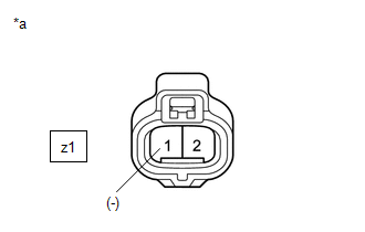
(a) Disconnect the z1 cooling fan motor connector.
| (b) Measure the resistance according to the value(s) in the table below. Standard Resistance:
|
|
(c) Reconnect the z1 cooling fan motor connector.
| NG | | REPLACE COOLING FAN MOTOR |
|
| 13. | CHECK HARNESS AND CONNECTOR (NO. 2 COOLING FAN MOTOR - BODY GROUND) |
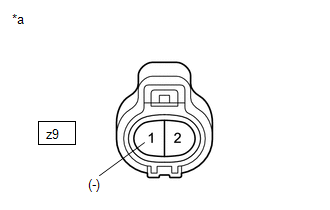
(a) Disconnect the z9 No. 2 cooling fan motor connector.
| (b) Measure the resistance according to the value(s) in the table below. Standard Resistance:
|
|
(c) Reconnect the z9 No. 2 cooling fan motor connector.
| OK | | REPLACE COOLING FAN ECU |
| NG | | REPLACE NO. 2 COOLING FAN MOTOR |
READ NEXT:
 Cooling System
On-vehicle InspectionON-VEHICLE INSPECTION PROCEDURE 1. INSPECT FOR COOLANT LEAK CAUTION: To avoid the danger of being burned, do not remove the radiator reservoir cap while the engine assembly and r
Components
COMPONENTS ILLUSTRATION *A for 2WD *B for AWD *1 HOOD LOCK ASSEMBLY *2 NO. 6 INVERTER BRACKET *3 UPPER RADIATOR SUPPORT SUB-ASSEMBLY *4 FRONT RADIATOR SIDE AIR GUIDE PLAT
SEE MORE:
Diagnostic Trouble Code Chart
DIAGNOSTIC TROUBLE CODE CHART Pre-collision System DTC No. Detection Item Link C142571 Stop Light Relay Actuator Stuck U012587 Lost Communication With Multi-axis Acceleration Sensor Module Missing Message U012687 Lost Communication with Steering Angle Sensor Module
System Description
SYSTEM DESCRIPTION
The theft deterrent system can be set/canceled by locking/unlocking the doors performing any of the following operation:
Entry lock/unlock operation
Wireless lock/unlock operation*1
Key linked lock/unlock operation
By opening and closing the doors*2
*1: Using the re
