Lexus NX: Disassembly
DISASSEMBLY
CAUTION / NOTICE / HINT
HINT:
- Use the same procedure for the RH and LH sides.
- The procedure listed below is for the LH side.
PROCEDURE
1. REMOVE NO. 1 MOULDING TAPE
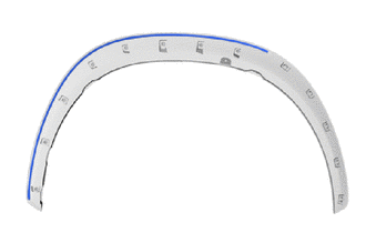
(a) Remove the No. 1 moulding tape (double-sided tape).
HINT:
Do not pull on the No. 1 moulding tape (double-sided tape). Instead, roll the tape up with your finger to remove it cleanly.
.png)
(b) Using non-residue solvent and a cloth, wipe off any No. 1 moulding tape (double-sided tape) remaining on the front fender moulding sub-assembly LH.
HINT:
If any No. 1 moulding tape (double-sided tape) remains in the groove of the front fender moulding sub-assembly LH, use a thin-bladed screwdriver to remove it.
2. REMOVE NO. 2 MOULDING TAPE
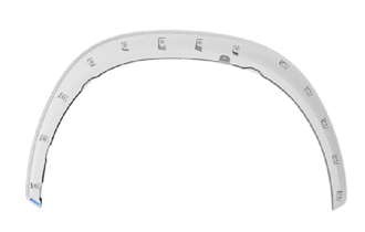
(a) Remove the No. 2 moulding tape (double-sided tape).
HINT:
Do not pull on the No. 2 moulding tape (double-sided tape). Instead, roll the tape up with your finger to remove it cleanly.
(b) Using non-residue solvent and a cloth, wipe off any No. 2 moulding tape (double-sided tape) remaining on the front fender moulding sub-assembly LH.
HINT:
If any No. 2 moulding tape (double-sided tape) remains in the groove of the front fender moulding sub-assembly LH, use a thin-bladed screwdriver to remove it.
READ NEXT:
 Reassembly
REASSEMBLY CAUTION / NOTICE / HINT HINT:
Use the same procedure for the RH and LH sides.
The procedure listed below is for the LH side.
PROCEDURE 1. INSTALL NO. 1 MOULDING TAPE (a) Clean the N
Installation
INSTALLATION CAUTION / NOTICE / HINT HINT:
Use the same procedure for the RH and LH sides.
The procedure listed below is for the LH side.
PROCEDURE 1. INSTALL FRONT FENDER MOULDING SUB-ASSEMBL
SEE MORE:
Idle Control System (P0505)
DESCRIPTION The idle speed is controlled by the electronic throttle control system. The electronic throttle control system is comprised of: 1) one valve type throttle body with motor assembly; 2) the throttle actuator, which operates the throttle valve; 3) the throttle position sensor, which detects
Turn Signal Switch Circuit
DESCRIPTION The combination meter receives the turn signal switch information and controls the turn signal lights. WIRING DIAGRAM CAUTION / NOTICE / HINT NOTICE: When replacing the combination meter assembly, make sure to replace it with a new one. PROCEDURE 1. READ VALUE USING TECHSTREAM (TU
