Lexus NX: Reassembly
REASSEMBLY
CAUTION / NOTICE / HINT
HINT:
- Use the same procedure for the RH and LH sides.
- The procedure listed below is for the LH side.
PROCEDURE
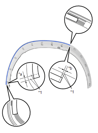
1. INSTALL NO. 1 MOULDING TAPE
(a) Clean the No. 1 moulding tape installation surface with a non-residue solvent.
(b) Apply primer to the No. 1 moulding tape installation area on the front fender moulding sub-assembly LH.
NOTICE:
Apply primer evenly so that there are no uncoated areas.
(c) Remove the peeling paper on a new No. 1 moulding tape while making sure not to touch the adhesional surface.
| (d) Install a new No. 1 moulding tape in the position shown in the illustration. NOTICE:
|
|
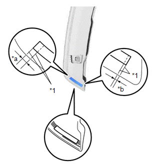
2. INSTALL NO. 2 MOULDING TAPE
(a) Clean the No. 2 moulding tape installation surface with a non-residue solvent.
(b) Apply primer to the No. 2 moulding tape installation area on the front fender moulding sub-assembly LH.
NOTICE:
Apply primer evenly so that there are no uncoated areas.
(c) Remove the peeling paper on a new No. 2 moulding tape while making sure not to touch the adhesional surface.
| (d) Install a new No. 2 moulding tape in the position shown in the illustration. NOTICE:
|
|
READ NEXT:
 Installation
INSTALLATION CAUTION / NOTICE / HINT HINT:
Use the same procedure for the RH and LH sides.
The procedure listed below is for the LH side.
PROCEDURE 1. INSTALL FRONT FENDER MOULDING SUB-ASSEMBL
Components
COMPONENTS ILLUSTRATION *1 QUARTER OUTSIDE MOULDING SUB-ASSEMBLY LH - - ILLUSTRATION *1 NO. 5 MOULDING TAPE *2 REAR LOWER QUARTER MOULDING PROTECTOR LH ● Non-reusable pa
SEE MORE:
Inspection
INSPECTION PROCEDURE 1. INSPECT ENGINE COOLANT TEMPERATURE SENSOR *a Component without harness connected (Engine Coolant Temperature Sensor) *b Resistance *c Temperature *d Acceptable Range (a) Partially immerse the sensor in water and warm up the water. (b) Measure the resist
If a warning light turns on or a warning
buzzer sounds
Calmly perform the following actions if any of the warning lights comes
on or
flashes. If a light comes on or flashes, but then goes off, this does not
necessarily
indicate a malfunction in the system. However, if this continues to occur,
have the vehicle inspected by your Lexus dealer.
Acti
