Lexus NX: Disassembly
DISASSEMBLY
PROCEDURE
1. PRECAUTION
NOTICE:
-
Be sure to read Precaution thoroughly before servicing.
Click here
.gif)
- Handle components indoors as much as possible to prevent foreign matter from entering and adhering to fog light assembly components.
- Do not reuse parts which have reduced fastening ability due to thread damage.
- Do not touch the inner surface of the lens and metallic surfaces as much as possible, or they may become dirty
- Do not allow metallic surfaces to become dirty, as such surfaces become damaged even if they are only lightly wiped with a soft cloth.
- When installing components, make sure that the wire harness is not pinched or pulled.
- Do not use solvent to clean components. Only clean them with a dry cloth.
HINT:
- Use the same procedure for the RH and LH sides.
- The procedure listed below is for the LH side.
2. REMOVE FOG LIGHT LENS LH
NOTICE:
- Perform work using clean rubber gloves.
- Do not touch the inner surface of the lens and metallic surfaces as much as possible, or they may become dirty.
- Do not allow metallic surfaces to become dirty, as such surfaces become damaged even if they are only lightly wiped with a soft cloth.
- Do not use solvent to clean components. Only clean them with a dry cloth.
| (a) Remove the 3 screws. |
|
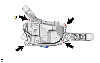
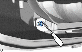
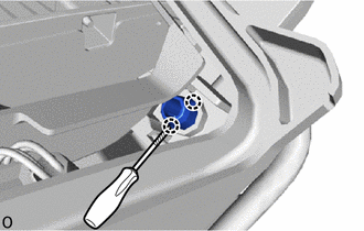
(b) Using a T20H "TORX" screwdriver, remove the screw.
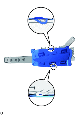
| (c) Detach the 2 claws. |
|
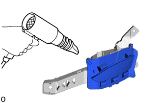
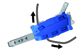
| (d) Using a dryer, heat the backside of the fog light assembly LH. NOTICE: If the fog light assembly is heated unevenly, it will deform or melt. |
|
(e) Insert a finger between the fog light lens LH and fog light housing and lift up the fog light lens LH.
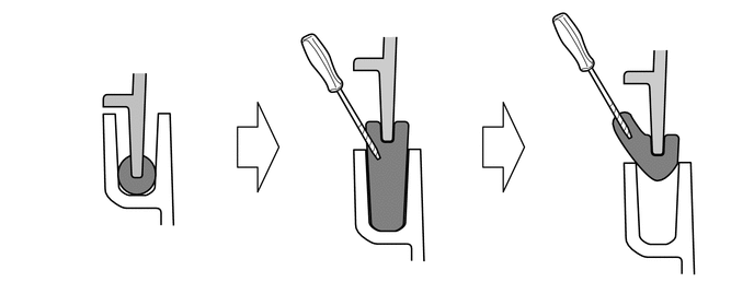
(f) Using a screwdriver, pull out the fog light gasket through the opening.
NOTICE:
Do not damage the groove in the fog light housing or the surface of the fog light lens LH.
HINT:
Tape the screwdriver tip before use.
.png) | Fog Light Housing |  | Fog Light Gasket |
 | Fog Light Lens LH | .png) | Protective Tape |
(g) Pull out the fog light lens LH until it detaches from the fog light gasket.
HINT:
If the fog light gasket is disconnected while being pulled out, lift up the fog light lens and pull the fog light gasket again.
| | Fog Light Gasket |
3. REMOVE FOG LIGHT GASKET
NOTICE:
- The fog light gasket must not be reused.
- Perform work using clean rubber gloves.
- Do not touch the inner surface of the lens and metallic surfaces as much as possible, or they may become dirty.
- Do not allow metallic surfaces to become dirty, as such surfaces become damaged even if they are only lightly wiped with a soft cloth.
- If there are fingerprints on the inner surface of the lens, lightly wiped with a soft cloth.
- Do not use solvent to clean components. Only clean them with a dry cloth.
(a) Remove the remaining fog light gasket from the fog light lens and fog light housing.
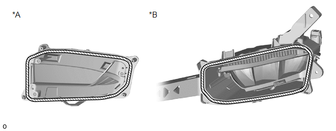
| *A | Fog Light Lens LH Side | *B | Fog Light Housing Side |
| | Fog light gasket | - | - |
4. REMOVE FOG LIGHT UNIT LH
NOTICE:
- Prevention of static electricity is required during this procedure.
- Use static electricity countermeasures SST (desktop anti-static mat set) and observe all precautions to prevent damage to the system by electrostatic discharge (ESD).
- Perform work using clean rubber gloves.
- Do not touch the fog light unit LH with bare hands.
- Do not allow metallic surfaces to become dirty, as such surfaces become damaged even if they are only lightly wiped with a soft cloth.
- If there are fingerprints on the inner surface of the lens, lightly wiped with a soft cloth.
- Do not use solvent to clean components. Only clean them with a dry cloth.
SST: 09890-47010
09891-04010
09891-04020
09891-04030
09891-04040
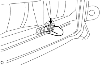
| (a) Disconnect the connector. |
|
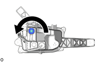
| (b) Loosen the aiming screw 20 rotations. |
|
| | Protective Tape |
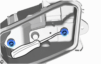
(c) Using a screwdriver, detach the 2 claws and disconnect the fog light unit LH from the pivot collar.
HINT:
Tape the screwdriver tip before use.
(d) Using a screwdriver, detach the 2 claws and disconnect the fog light unit LH from the pivot collar.
| | Protective Tape |
HINT:
If it is difficult to insert the screw, loosen the aiming screw until the pivot collar can be contacted. However, make sure to count and record the number of rotations when loosening the aiming screw.
(e) While holding the fog light unit LH with one hand so that it does not fall over, loosen the aiming screw until the fog light unit LH is disconnected.
HINT:
Count and record the number of rotations before the fog light unit LH and aiming screw are disconnected.
(f) Using a clip remover, remove the 2 pivot collar.
HINT:
Tape the clip remover tip before use.
| | Protective Tape |
(g) Install the removed 2 pivot collars to the fog light unit LH.
READ NEXT:
 Inspection
INSPECTION PROCEDURE 1. INSPECT FOG LIGHT ASSEMBLY LH (a) Apply battery voltage to the connector and check the light illumination condition. OK: Battery Connection Specified Condition Pos
Adjustment
ADJUSTMENT CAUTION / NOTICE / HINT HINT:
Use the same procedure for the RH and LH sides.
The procedure listed below is for the LH side.
PROCEDURE 1. PREPARE VEHICLE FOR FOG LIGHT AIM ADJUSTMEN
Reassembly
REASSEMBLY CAUTION / NOTICE / HINT NOTICE:
Handle components indoors as much as possible to prevent foreign matter from entering and adhering to fog light assembly components.
Do not reuse parts
SEE MORE:
Knock Sensor 1 Circuit Low Input (Bank 1 or Single Sensor) (P0327,P0328)
DESCRIPTION A flat type knock control sensor (non-resonant type) has a structure that can detect vibration between approximately 5 kHz and 23 kHz. The knock control sensors are fitted onto the engine block to detect engine knocking. The knock control sensor contains a piezoelectric element which gen
Climate Control System does not Operate on Driver Side
DESCRIPTION The air conditioning control assembly sends operation signals to the air conditioning amplifier assembly via the LIN communication line. The air conditioning amplifier assembly actives the seat blowers according these signals. WIRING DIAGRAM CAUTION / NOTICE / HINT NOTICE:
The climat
