Lexus NX: Inspection
INSPECTION
PROCEDURE
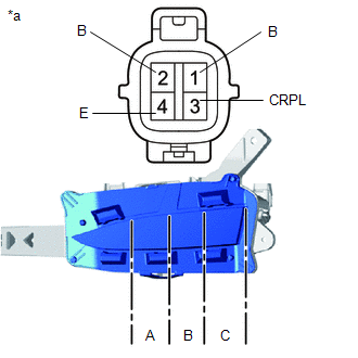
1. INSPECT FOG LIGHT ASSEMBLY LH
| (a) Apply battery voltage to the connector and check the light illumination condition. OK:
HINT: If the result is not as specified, replace the fog light assembly LH. |
|
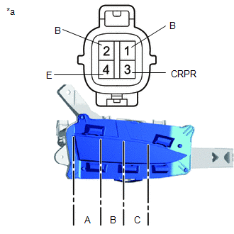
2. INSPECT FOG LIGHT ASSEMBLY RH
| (a) Apply battery voltage to the connector and check the light illumination condition. OK:
HINT: If the result is not as specified, replace the fog light assembly RH. |
|
READ NEXT:
 Adjustment
ADJUSTMENT CAUTION / NOTICE / HINT HINT:
Use the same procedure for the RH and LH sides.
The procedure listed below is for the LH side.
PROCEDURE 1. PREPARE VEHICLE FOR FOG LIGHT AIM ADJUSTMEN
Reassembly
REASSEMBLY CAUTION / NOTICE / HINT NOTICE:
Handle components indoors as much as possible to prevent foreign matter from entering and adhering to fog light assembly components.
Do not reuse parts
Installation
INSTALLATION CAUTION / NOTICE / HINT HINT:
Use the same procedure for the RH and LH sides.
The procedure described below is for the LH side.
PROCEDURE 1. INSTALL FOG LIGHT ASSEMBLY LH (a) Inst
SEE MORE:
Installation
INSTALLATION CAUTION / NOTICE / HINT HINT:
Use the same procedure for the RH and LH sides.
The procedure listed below is for the LH side.
PROCEDURE 1. INSTALL SIDE MUDGUARD SUB-ASSEMBLY LH HINT: When installing the side mudguard sub-assembly LH, heat the vehicle body and side mudguard sub-as
Fr Sensor Initialization Incomplete (C1AF3)
DESCRIPTION When it is judged that the front sensors have not been initialized, the clearance warning ECU assembly stores DTC C1AF3. DTC No. Detection Item DTC Detection Condition Trouble Area C1AF3 Fr Sensor Initialization Incomplete Front sensor not initialized
Initialize fro
