Lexus NX: Drive Motor "A" Temperature Sensor Circuit Low (P0A2C-247,P0A2D-249)
DESCRIPTION
Refer to the description for DTC P0A2B-250.
Click here .gif)
| DTC No. | Detection Item | DTC Detection Condition | Trouble Area | MIL | Warning Indicate |
|---|---|---|---|---|---|
| P0A2C-247 | Drive Motor "A" Temperature Sensor Circuit Low | Line short or short to ground in the motor temperature sensor circuit (1 trip detection logic) |
| Comes on | Master Warning Light: Comes on |
| P0A2D-249 | Drive Motor "A" Temperature Sensor Circuit High | Open or short to +B in the motor temperature sensor circuit (1 trip detection logic) |
| Comes on | Master Warning Light: Comes on |
| DTC No. | Data List |
|---|---|
| P0A2C-247 | Motor Temp No1 |
| P0A2D-249 |
HINT:
After confirming that DTC P0A2C-247 or P0A2D-249 is output, use the Techstream to check "Motor Temp No1" in the Data List.
| Displayed Temperature | Malfunction |
|---|---|
| -40°C (-40°F) | Open circuit or short to +B |
| 215°C (419°F) | Short circuit or short to ground |
MONITOR DESCRIPTION
If the hybrid vehicle control ECU detects a malfunction of the motor temperature sensor, it will illuminate the MIL and store a DTC.
MONITOR STRATEGY
| Related DTCs | P0A2C (INF 247): Drive Motor "A" Temperature Sensor Circuit Low P0A2D (INF 249): Drive Motor "A" Temperature Sensor Circuit High |
| Required sensors / components | Motor temperature sensor |
| Frequency of operation | Continuous |
| Duration | TMC's intellectual property |
| MIL operation | 1 driving cycle |
| Sequence of operation | None |
TYPICAL ENABLING CONDITIONS
| The monitor will run whenever the following DTCs are not present | TMC's intellectual property |
| Other conditions belong to TMC's intellectual property | - |
TYPICAL MALFUNCTION THRESHOLDS
| TMC's intellectual property | - |
COMPONENT OPERATING RANGE
| Hybrid vehicle control ECU assembly | DTC P0A2C (INF 247) is not detected DTC P0A2D (INF 249) is not detected |
CONFIRMATION DRIVING PATTERN
HINT:
After the repair, clear the DTCs and perform the following procedure to check that DTCs are not output.
- Connect the Techstream to the DLC3.
- Turn the power switch on (IG) and turn the Techstream on.
- Clear the DTCs (even if no DTCs are stored, perform the clear DTC procedure).
- Turn the power switch off and wait for 2 minutes or more.
- Turn the power switch on (IG) and turn the Techstream on.
- With power switch on (IG) and wait for 5 seconds or more.
- Enter the following menus: Powertrain / Hybrid Control / Trouble Codes.
-
Read the current DTCs.
HINT:
- If a current DTC is output, the system is malfunctioning.
- If a current DTC is not output, perform the following procedure.
- Check that permanent DTCs are cleared. If no permanent DTC is output, the system is normal.
- If the permanent DTCs are not cleared, perform the universal trip, and then check for permanent DTCs again.
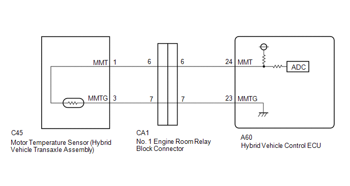
WIRING DIAGRAM
PROCEDURE
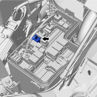
| 1. | CHECK CONNECTOR CONNECTION CONDITION (HYBRID VEHICLE CONTROL ECU CONNECTOR) |
| (a) Check the connection condition of the hybrid vehicle control ECU connectors and the contact pressure of each terminal. Check the terminals for deformation, and check the connector for water ingress and foreign matter. Click here OK: - The connector is connected securely. - The terminals are not deformed and are connected securely. - No water or foreign matter in the connector.
|
|
| B | .gif) | CONNECT SECURELY |
| C | | REPAIR OR REPLACE HARNESS OR CONNECTOR |
|
.gif)
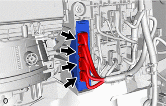
| 2. | CHECK CONNECTOR CONNECTION CONDITION (NO. 1 ENGINE ROOM RELAY BLOCK AND JUNCTION BLOCK ASSEMBLY CA1 CONNECTOR) |
| (a) Check the connection condition of the No. 1 engine room relay block and junction block assembly CA1 connector and the contact pressure of each terminal. Check the terminals for deformation, and check the connector for water ingress and foreign matter. Click here OK: - The connector is connected securely. - The terminals are not deformed and are connected securely. - No water or foreign matter in the connectors. |
|
| Result | Proceed to |
|---|---|
| OK | A |
| NG (The connector is not connected securely.) | B |
| NG (The terminals are not making secure contact or are deformed, or water or foreign matter exists in the connector.) | C |
| B | | CONNECT SECURELY |
| C | | REPAIR OR REPLACE HARNESS OR CONNECTOR |
|
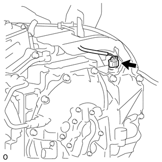
| 3. | CHECK CONNECTOR CONNECTION CONDITION (MOTOR TEMPERATURE SENSOR CONNECTOR) |
| (a) Check the connection condition of the motor temperature sensor connector and the contact pressure of each terminal. Check the terminals for deformation, and check the connector for water ingress and foreign matter. Click here OK: - The connector is connected securely. - The terminals are not deformed and are connected securely. - No water or foreign matter in the connector. |
|
| Result | Proceed to |
|---|---|
| OK | A |
| NG (The connector is not connected securely.) | B |
| NG (The terminals are not making secure contact or are deformed, or water or foreign matter exists in the connector.) | C |
| B | | CONNECT SECURELY |
| C | | REPAIR OR REPLACE HARNESS OR CONNECTOR |
|
| 4. | READ VALUE USING TECHSTREAM (MOTOR TEMP NO1) |
(a) Connect the Techstream to the DLC3.
(b) Turn the power switch on (IG).
(c) Enter the following menus: Powertrain / Hybrid Control / Data List / Motor Temp No1.
Powertrain > Hybrid Control > Data List| Tester Display |
|---|
| Motor Temp No1 |
(d) Read the Data List.
(e) Turn the power switch off.
| 215°C (419°F) | | GO TO STEP 7 |
| Same as actual temperature | | REPAIR OR REPLACE HARNESS OR CONNECTOR |
|
| 5. | INSPECT HYBRID VEHICLE TRANSAXLE ASSEMBLY (MOTOR TEMPERATURE SENSOR) |
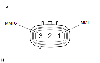
| (a) Disconnect the C45 motor temperature sensor connector. |
|
| (b) Measure the resistance according to the value(s) in the table below. Standard Resistance:
|
|
(c) Reconnect the C45 motor temperature sensor connector.
| NG | | REPLACE HYBRID VEHICLE TRANSAXLE ASSEMBLY |
|
| 6. | CHECK HYBRID VEHICLE CONTROL ECU |
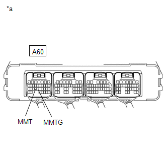
(a) Connect terminals 24 (MMT) and 23 (MMTG) of the A60 hybrid vehicle control ECU connector.
(b) Connect the Techstream to the DLC3.
| (c) Turn the power switch on (IG). |
|
(d) Enter the following menus: Powertrain / Hybrid Control / Data List / Motor Temp No1.
Powertrain > Hybrid Control > Data List| Tester Display |
|---|
| Motor Temp No1 |
(e) Read the Data List.
OK:
| Tester Display | Condition | Specified Condition |
|---|---|---|
| Motor Temp No1 | Terminals A60-24 (MMT) and A60-23 (MMTG) connected Power switch on (IG) | 215°C (419°F) |
(f) Turn the power switch off.
| OK | | REPAIR OR REPLACE HARNESS OR CONNECTOR |
| NG | | REPLACE HYBRID VEHICLE CONTROL ECU |
| 7. | INSPECT HYBRID VEHICLE TRANSAXLE ASSEMBLY (MOTOR TEMPERATURE SENSOR) |
| (a) Disconnect the C45 motor temperature sensor connector. |
|
| (b) Measure the resistance according to the value(s) in the table below. Standard Resistance:
|
|
(c) Reconnect the C45 motor temperature sensor connector.
| NG | | REPLACE HYBRID VEHICLE TRANSAXLE ASSEMBLY |
|
| 8. | CHECK HARNESS AND CONNECTOR (MOTOR TEMPERATURE SENSOR - HYBRID VEHICLE CONTROL ECU) |
(a) Disconnect the C45 motor temperature sensor connector.
(b) Disconnect the A60 hybrid vehicle control ECU connector.
(c) Measure the resistance according to the value(s) in the table below.
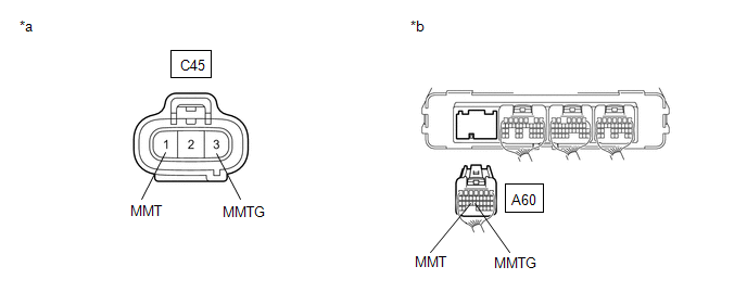
| *a | Front view of wire harness connector (to Motor Temperature Sensor) | *b | Rear view of wire harness connector (to Hybrid Vehicle Control ECU) |
Standard Resistance (Check for Open):
| Tester Connection | Condition | Specified Condition |
|---|---|---|
| C45-1 (MMT) - A60-24 (MMT) | Power switch off | Below 1 Ω |
| C45-3 (MMTG) - A60-23 (MMTG) | Power switch off | Below 1 Ω |
Standard Resistance (Check for Short):
| Tester Connection | Condition | Specified Condition |
|---|---|---|
| C45-1 (MMT) or A60-24 (MMT) - Body ground and other terminals | Power switch off | 10 kΩ or higher |
| C45-3 (MMTG) or A60-23 (MMTG) - Body ground and other terminals | Power switch off | 10 kΩ or higher |
(d) Reconnect the A60 hybrid vehicle control ECU connector.
(e) Reconnect the C45 motor temperature sensor connector.
| OK | | REPLACE HYBRID VEHICLE CONTROL ECU |
| NG | | REPAIR OR REPLACE HARNESS OR CONNECTOR |
READ NEXT:
 Drive Motor "B" Temperature Sensor Circuit Range / Performance (P0A31-668,P0A34-667)
DESCRIPTION The resistance of the thermistor built into the rear motor temperature sensor changes in accordance with changes in the rear motor temperature. The lower the rear motor temperature, the hi
Drive Motor "B" Temperature Sensor Circuit Low (P0A32-666,P0A33-665)
DESCRIPTION Refer to the description for DTC P0A31-668. Click here HINT: The term "drive motor B" indicates the rear motor (MGR). DTC No. Detection Item DTC Detection Condition Trouble Area
Generator Temperature Sensor Circuit Range / Performance (P0A37-260,P0A3A-258)
DESCRIPTION The resistance of the thermistor built into the generator temperature sensor changes in accordance with changes in generator (MG1) temperature. The lower the generator (MG1) temperature, t
SEE MORE:
On-vehicle Inspection
ON-VEHICLE INSPECTION PROCEDURE 1. INSPECT STOP LIGHT SWITCH ASSEMBLY (a) Disconnect the stop light switch assembly connector. *a Front view of wire harness connector (to Stop Light Switch Assembly) (b) Measure the voltage and resistance on the wire harness side connector
Dtc Check / Clear
DTC CHECK / CLEAR CHECK FOR DTC (a) Turn the power switch off. (b) Connect the Techstream to the DLC3. (c) Turn the power switch on (IG). (d) Turn the Techstream on. (e) Enter the following menus: Body Electrical / Back Door / Trouble Codes. (f) Check for DTCs. Body Electrical > Back Door > Tr
