Lexus NX: Headlight Cleaner Actuator
Components
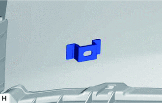
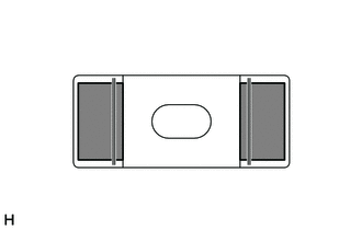
COMPONENTS
ILLUSTRATION
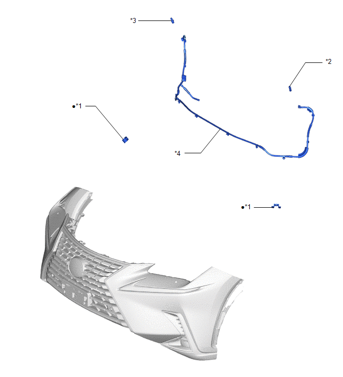
| *1 | HEADLIGHT CLEANER WASHER BRACKET | *2 | HEADLIGHT WASHER ACTUATOR SUB-ASSEMBLY LH |
| *3 | HEADLIGHT WASHER ACTUATOR SUB-ASSEMBLY RH | *4 | NO. 2 HEADLIGHT CLEANER HOSE |
| ● | Non-reusable part | - | - |
Removal
REMOVAL
PROCEDURE
1. REMOVE FRONT BUMPER ASSEMBLY
(a) Remove the front bumper assembly.
(1) for Sport Package:
Click here .gif)
(2) except Sport Package:
Click here
2. REMOVE HEADLIGHT WASHER ACTUATOR SUB-ASSEMBLY RH
| (a) Detach the claw and disconnect the No. 2 headlight cleaner hose as shown in the illustration. |
|
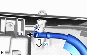
| (b) Detach the claw and remove the headlight washer actuator sub-assembly RH. |
|
3. REMOVE HEADLIGHT WASHER ACTUATOR SUB-ASSEMBLY LH
HINT:
Use the same procedure described for the RH side.
4. REMOVE NO. 2 HEADLIGHT CLEANER HOSE
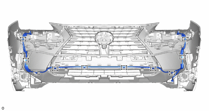
(a) Detach the 10 clamps and remove the No. 2 headlight cleaner hose.
5. REMOVE HEADLIGHT CLEANER WASHER BRACKET
HINT:
Use the same procedure for both headlight cleaner washer brackets.
| (a) While heating the headlight cleaner washer bracket using a dryer, pull the headlight cleaner washer bracket lightly and remove the double-sided tape. Then remove the headlight cleaner washer bracket. Heating temperature: 40 to 60°C (104 to 140°F) CAUTION: Be careful of burns. |
|
(b) Using a cloth or non-residue solvent, wipe off any tape residue on the front bumper cover.
Installation
INSTALLATION
PROCEDURE
1. INSTALL HEADLIGHT CLEANER WASHER BRACKET
HINT:
Use the same procedure for both headlight cleaner washer brackets.
(a) Clean the front bumper cover surface.
(1) Remove the double-sided tape from the front bumper cover.
(2) Wipe off any tape adhesive residue with cleaner.
(b) Apply primer.
.png) | Primer |
(1) Using a brush or felt, apply primer or equivalent to the retainer installation area.
NOTICE:
- Use a clean brush or felt.
- Do not allow primer to contact the front surface of the front bumper cover.
(2) Do not touch the front bumper cover until the primer has dried.
Recommended drying time:
10 minutes or more {23°C (73°F)}
(c) Peel off the release paper from the headlight cleaner washer bracket.
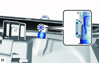
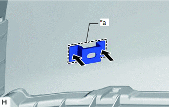
| (d) Align the headlight cleaner washer bracket with the mark on the front bumper cover and install it as shown in the illustration. NOTICE: The double-sided tape of a headlight cleaner washer bracket will deteriorate if it is detached. Make sure to replace the headlight cleaner washer bracket with a new one when reattachment is necessary. HINT: Press on the areas indicated by the arrows in the illustration and install the headlight cleaner washer bracket firmly so that there is no clearance between the headlight cleaner washer bracket and front bumper cover. |
|
2. INSTALL NO. 2 HEADLIGHT CLEANER HOSE
(a) Attach the 10 clamps to install the No. 2 headlight cleaner hose.
3. INSTALL HEADLIGHT WASHER ACTUATOR SUB-ASSEMBLY RH
(a) Attach the claw to install the headlight washer actuator sub-assembly RH.
(b) Attach the claw to connect the headlight cleaner hose.
4. INSTALL HEADLIGHT WASHER ACTUATOR SUB-ASSEMBLY LH
HINT:
Use the same procedure described for the RH side.
5. INSTALL FRONT BUMPER ASSEMBLY
(a) Install the front bumper assembly.
(1) for Sport Package:
Click here .gif)
(2) except Sport Package:
Click here
READ NEXT:
 Headlight Cleaner Actuator Cover
ComponentsCOMPONENTS ILLUSTRATION *1 HEADLIGHT CLEANER WASHER NOZZLE COVER LH *2 HEADLIGHT CLEANER WASHER NOZZLE COVER RH *3 HEADLIGHT WASHER ACTUATOR SUB-ASSEMBLY LH *4 HEADLIGHT
Headlight Cleaner Control Relay (for Single Beam Headlight)
ComponentsCOMPONENTS ILLUSTRATION *1 FRONT BUMPER COVER *2 HEADLIGHT CLEANER CONTROL RELAY On-vehicle InspectionON-VEHICLE INSPECTION PROCEDURE 1. INSPECT HEADLIGHT CLEANER CONTROL RELA
Headlight Cleaner Control Relay(for Triple Beam Headlight)
On-vehicle InspectionON-VEHICLE INSPECTION PROCEDURE 1. INSPECT HEADLIGHT CLEANER CONTROL RELAY (a) Remove the headlight cleaner control relay. (b) Measure the resistance according to the value(s)
SEE MORE:
Initialization
INITIALIZATION INITIALIZATION SERVO MOTOR (a) Turn the power switch off. (b) Connect the Techstream to the DLC3. (c) Turn the power switch on (IG). (d) Press the A/C OFF switch. (e) Turn the Techstream on. (f) Enter the following menus: Body Electrical / Air Conditioner / Utility / Servomotor Initia
Installation
INSTALLATION PROCEDURE 1. INSTALL TIMING CHAIN COVER OIL SEAL (a) w/o Side Lip: (1) Apply MP grease to the lip of a new timing chain cover oil seal. NOTICE:
Do not allow foreign matter to contact the lip of the timing chain cover oil seal.
Do not allow MP grease to contact the dust seal.
