Lexus NX: Inspection
INSPECTION
PROCEDURE
1. INSPECT AIR CONDITIONING THERMISTOR ASSEMBLY (HUMIDITY SENSOR)
(a) for Glass temperature sensor:
(1) Measure the resistance according to the value(s) in the table below.

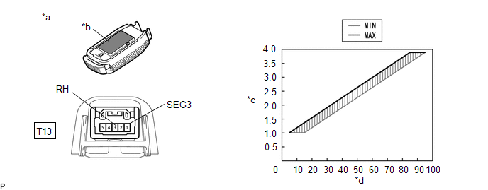
| *a | Component without harness connected (Air Conditioning Thermistor Assembly (Glass Temperature Sensor)) | *b | Heat Conduction Sheet Part |
| *c | Resistance (kΩ) | *d | Temperature (°C (°F)) |
| Tester Connection | Condition | Specified Condition |
|---|---|---|
| T13-1(SEG3) - T13-4(TFG) | 10°C (50°F) | 5.92 to 6.09 kΩ |
| 15°C (59°F) | 4.94 to 5.07 kΩ | |
| 20°C (68°F) | 4.20 to 4.29 kΩ | |
| 25°C (77°F) | 3.64 to 3.70 kΩ | |
| 30°C (86°F) | 3.19 to 3.26 kΩ | |
| 35°C (95°F) | 2.85 to 2.91 kΩ | |
| 40°C (104°F) | 2.58 to 2.64 kΩ | |
| 45°C (113°F) | 2.37 to 2.43 kΩ | |
| 50°C (122°F) | 2.21 to 2.26 kΩ | |
| 55°C (131°F) | 2.07 to 2.12 kΩ | |
| 60°C (140°F) | 1.97 to 2.01 kΩ |
NOTICE:
- Hold the sensor only by its connector.Touching the sensor may change the resistance value.
- When measuring, the sensor temperature must be the same as the ambient temperature.
HINT:
- As the humidity increases, the voltage increases (see the graph).
- If the resistance is not as specified, replace the air conditioning thermistor assembly (glass temperature sensor).
(b) for Humidity sensor:
(1) Remove the air conditioning thermistor assembly (humidity sensor) with the connector still connected.
(2) Turn the power switch on (IG).
(3) Measure the voltage according to the value(s)in the table below.
| *a | Component without harness connected (Air Conditioning Thermistor Assembly (Humidity Sensor)) | *b | Heat Conduction Sheet Part |
| *c | Voltage (V) | *d | Relative Humidity (%) |
| Tester Connection | Condition | Specified Condition |
|---|---|---|
| T13-1(SEG3) - T13-3(RH) | IG ON Humidity is 5 to 15 % | 1.01 V |
| IG ON Humidity is 15 to 25 % | 1.37 V | |
| IG ON Humidity is 25 to 35 % | 1.73 V | |
| IG ON Humidity is 35 to 45 % | 2.09 V | |
| IG ON Humidity is 45 to 55 % | 2.45 V | |
| IG ON Humidity is 55 to 65 % | 2.81 V | |
| IG ON Humidity is 65 to 75 % | 3.17 V | |
| IG ON Humidity is 75 to 85% | 3.53 V | |
| IG ON Humidity is 85 to 95 % | 3.89 V |
NOTICE:
- Do not touch the sensor as body heat will affect the inspection results. When performing the inspection, hold the sensor by its connector.
- Allow the sensor to acclimate to the ambient temperature and humidity before performing the inspection.
- The specified voltages in the table above are based on inspections performed when the ambient temperature is 25°C(77°F).
HINT:
- As the humidity increases, the voltage increases (see the graph).
- If the voltage is not as specified, replace the air conditioning thermistor assembly (humidity sensor).
(c) for Glass surroundings temperature sensor:
(1) Measure the resistance according to the value(s) in the table below.
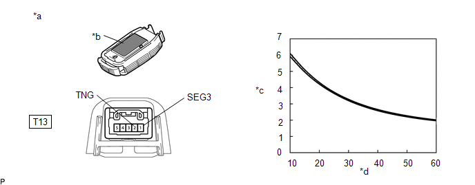
| *a | Component without harness connected (Air Conditioning Thermistor Assembly (Glass Surroundings Temperature Sensor)) | *b | Heat Conduction Sheet Part |
| *c | Resistance (kΩ) | *d | Temperature (°C (°F)) |
| Tester Connection | Condition | Specified Condition |
|---|---|---|
| T13-1(SEG3) - T13-2(TNG) | 10°C (50°F) | 5.92 to 6.09 kΩ |
| 15°C (59°F) | 4.94 to 5.07 kΩ | |
| 20°C (68°F) | 4.20 to 4.29 kΩ | |
| 25°C (77°F) | 3.64 to 3.70 kΩ | |
| 30°C (86°F) | 3.19 to 3.26 kΩ | |
| 35°C (95°F) | 2.85 to 2.91 kΩ | |
| 40°C (104°F) | 2.58 to 2.64 kΩ | |
| 45°C (113°F) | 2.37 to 2.43 kΩ | |
| 50°C (122°F) | 2.21 to 2.26 kΩ | |
| 55°C (131°F) | 2.07 to 2.12 kΩ | |
| 60°C (140°F) | 1.97 to 2.01 kΩ |
NOTICE:
- Hold the sensor only by its connector.Touching the sensor may change the resistance value.
- When measuring, the sensor temperature must be the same as the ambient temperature.
HINT:
As the humidity increases, the voltage increases (see the graph).
If the resistance is not as specified, replace the air conditioning thermistor assembly (glass surroundings temperature sensor).
READ NEXT:
 Installation
INSTALLATION PROCEDURE 1. INSTALL AIR CONDITIONING THERMISTOR ASSEMBLY (HUMIDITY SENSOR) *1 Stopper *2 Bracket (a) Attach the 2 brackets, and carefully install the air conditioning ther
Components
COMPONENTS ILLUSTRATION *1 NO. 1 AIR DUCT *2 QUICK HEATER ASSEMBLY ● Non-reusable part - -
SEE MORE:
Door Courtesy Switch Circuit
DESCRIPTION The main body ECU (multiplex network body ECU) receives a door open or closed signal from each door courtesy light switch. WIRING DIAGRAM CAUTION / NOTICE / HINT NOTICE:
Recognition code registration is necessary when replacing the main body ECU (multiplex network body ECU).
If the
Inspection
INSPECTION PROCEDURE 1. INSPECT OUTER MIRROR SWITCH ASSEMBLY (w/ Memory) (a) Check the mirror retract switch. (1) Measure the resistance according to the value(s) in the table below. Standard Resistance: Tester Connection Condition Specified Condition 8 (MR) - 10 (E) Driving positio
