Lexus NX: Inspection
INSPECTION
PROCEDURE
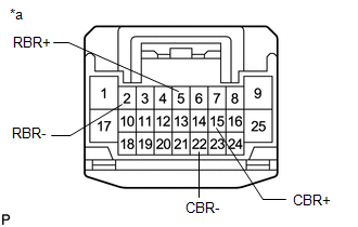
1. INSPECT REAR SEAT INNER WITH CENTER BELT ASSEMBLY RH
(a) for Manual Seat:
| (1) w/o Seat Heater System: Measure the resistance according to the value(s) in the table below. Standard Resistance:
If the result is not as specified, replace the rear seat inner with center belt assembly RH. |
|
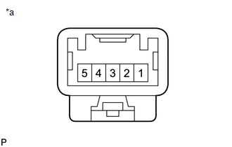
| (2) w/ Seat Heater System: Measure the resistance according to the value(s) in the table below. Standard Resistance:
If the result is not as specified, replace the rear seat inner with center belt assembly RH. |
|
(b) for Power Seat:
| (1) Measure the resistance according to the value(s) in the table below. Standard Resistance:
If the result is not as specified, replace the rear seat inner with center belt assembly RH. |
|
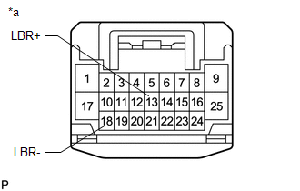
2. INSPECT REAR SEAT INNER BELT ASSEMBLY LH
(a) for Manual Seat:
| (1) w/o Seat Heater System: Measure the resistance according to the value(s) in the table below. Standard Resistance:
If the result is not as specified, replace the rear seat inner belt assembly LH. |
|
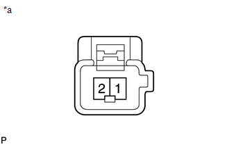
| (2) w/ Seat Heater System: Measure the resistance according to the value(s) in the table below. Standard Resistance:
If the result is not as specified, replace the rear seat inner belt assembly LH. |
|
(b) for Power Seat:
| (1) Measure the resistance according to the value(s) in the table below. Standard Resistance:
If the result is not as specified, replace the rear seat inner belt assembly LH. |
|
READ NEXT:
 Installation
INSTALLATION PROCEDURE 1. INSTALL REAR SEAT CENTER LAP TYPE BELT ASSEMBLY LH (a) Install the rear seat center lap type belt assembly LH with the nut. Torque: 42 N·m {428 kgf·cm, 31 ft·lbf} NOTI
Components
COMPONENTS ILLUSTRATION *1 DECK FLOOR BOX LH *2 NO. 3 DECK BOARD SUB-ASSEMBLY *3 REAR DECK FLOOR BOX *4 NEGATIVE AUXILIARY BATTERY TERMINAL N*m (kgf*cm, ft.*lbf): Specified
SEE MORE:
Steering Pad Switch Circuit
DESCRIPTION This circuit sends an operation signal from the steering pad switch assembly to the radio receiver assembly. If there is an open in the circuit, the audio system cannot be operated using the steering pad switch assembly. If there is a short in the circuit, the same condition as when a sw
Drive Motor "B" Position Sensor Circuit Range / Performance (P0A46-171)
DTC SUMMARY MALFUNCTION DESCRIPTION This DTC indicates that a large current flowed in the boost converter. The cause of this malfunction may be one of the following: Internal inverter malfunction
Inverter internal circuit malfunction
Rear traction motor with transaxle assembly malfunction
A
