Lexus NX: Installation
INSTALLATION
CAUTION / NOTICE / HINT
HINT:
Perform "Inspection After Repair" after replacing the EGR valve assembly.
Click here .gif)
PROCEDURE
1. INSTALL EGR VALVE ASSEMBLY
HINT:
Perform "Inspection After Repair" after replacing the EGR valve assembly.
Click here
| (a) Install 2 new gaskets to the No. 1 EGR pipe and intake manifold. NOTICE: Make sure that the gasket is installed in the correct direction. |
|
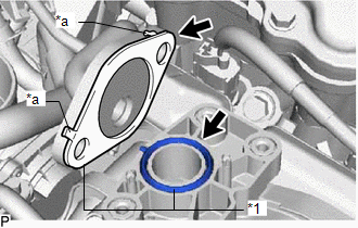
(b) Temporarily install the EGR valve assembly to the intake manifold with the 3 bolts.
(c) Connect the No. 1 EGR pipe to the EGR valve assembly and temporarily install the 2 nuts.
(d) Tighten the 3 bolts.
Torque:
10 N·m {102 kgf·cm, 7 ft·lbf}
(e) Using a 12 mm deep socket wrench, tighten the 2 nuts.
Torque:
21 N·m {214 kgf·cm, 15 ft·lbf}
(f) Using a 10 mm deep socket wrench, install the engine cover joint to the EGR valve assembly.
Torque:
10 N·m {102 kgf·cm, 7 ft·lbf}
(g) Connect the No. 1 water by-pass hose and No. 2 water by-pass hose to the EGR valve assembly, and slide the 2 clamps to secure the hose.
(h) Connect the connector to the EGR valve assembly.
2. INSTALL AIR CLEANER CAP AND HOSE
Click here
3. INSTALL NO. 1 ENGINE COVER SUB-ASSEMBLY
Click here
4. ADD ENGINE COOLANT
Click here
5. INSPECT FOR COOLANT LEAK
Click here
READ NEXT:
 Parts Location
PARTS LOCATION ILLUSTRATION *1 AIR FUEL RATIO SENSOR (for Bank 1 Sensor 1) *2 CHARCOAL CANISTER ASSEMBLY *3 EGR VALVE ASSEMBLY *4 FUEL TANK CAP ASSEMBLY *5 HEATED OXYGEN SENS
System Diagram
SYSTEM DIAGRAM *1 ECM *2 Engine Coolant Temperature Sensor *3 Air Fuel Ratio Sensor (for Bank 1 Sensor 1) *4 Heated Oxygen Sensor (for Bank 1 Sensor 2) *5 Crankshaft Position
SEE MORE:
Check Bus 5 Lines for Short Circuit
DESCRIPTION There may be a short circuit between the bus CAN main bus lines and/or CAN branch lines when the resistance between terminals 15 (CA5H) and 16 (CA5L) of the central gateway ECU (network gateway ECU) is below 54 Ω. Symptom Trouble Area
*1: w/ Pre-collision System
*2: w/ Intuitiv
Illumination for Panel Switch does not Come on with Tail Switch ON
CAUTION / NOTICE / HINT NOTICE: When replacing the radio receiver assembly, always replace it with a new one. If a radio receiver assembly which was installed to another vehicle is used, the following may occur:
A communication malfunction DTC may be stored.
The radio receiver assembly may not
