Lexus NX: Parts Location
Lexus NX Service Manual / Engine & Hybrid System / 2ar-fxe (emission Control) / Emission Control System / Parts Location
PARTS LOCATION
ILLUSTRATION
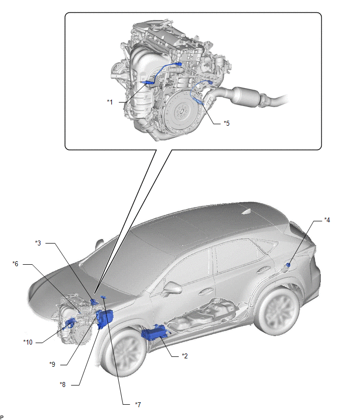
| *1 | AIR FUEL RATIO SENSOR (for Bank 1 Sensor 1) | *2 | CHARCOAL CANISTER ASSEMBLY |
| *3 | EGR VALVE ASSEMBLY | *4 | FUEL TANK CAP ASSEMBLY |
| *5 | HEATED OXYGEN SENSOR (for Bank 1 Sensor 2) | *6 | PCV VALVE |
| *7 | PURGE VSV | *8 | NO. 1 ENGINE ROOM RELAY BLOCK AND JUNCTION BLOCK - EFI NO. 1 FUSE - EFI NO. 2 FUSE |
| *9 | ECM | *10 | EGR COOLER ASSEMBLY |
READ NEXT:
 System Diagram
SYSTEM DIAGRAM *1 ECM *2 Engine Coolant Temperature Sensor *3 Air Fuel Ratio Sensor (for Bank 1 Sensor 1) *4 Heated Oxygen Sensor (for Bank 1 Sensor 2) *5 Crankshaft Position
On-vehicle Inspection
ON-VEHICLE INSPECTION PROCEDURE 1. VISUALLY INSPECT HOSES, CONNECTIONS AND GASKETS (a) Visually check that the hoses, connections and gaskets have no cracks, leaks or damage. NOTICE:
Detachment or
Fuel Tank Cap
InspectionINSPECTION PROCEDURE 1. INSPECT FUEL TANK CAP ASSEMBLY (a) Visually check that the fuel tank cap assembly and fuel tank cap gasket are not deformed or damaged. *1 Fuel Tank Cap Gasket
SEE MORE:
Blind Spot Monitor Sensor
RemovalREMOVAL CAUTION / NOTICE / HINT NOTICE:
Avoid any impact to the blind spot monitor sensor.
Do not drop the blind spot monitor sensor. If it is dropped, replace it with a new one.
PROCEDURE 1. REMOVE REAR BUMPER COVER Click here 2. REMOVE BLIND SPOT MONITOR SENSOR LH (a) Remove the
Dtc Check / Clear
DTC CHECK / CLEAR DTC CHECK (a) Turn the power switch off. (b) Connect the Techstream to the DLC3. (c) Turn the power switch on (IG). (d) Turn the Techstream on. (e) Enter the following menus: Body Electrical / Occupant Detection / Trouble Codes. (f) Check for DTCs by following the prompts on the Te
© 2016-2026 Copyright www.lexunx.com
