- - ECU-IG NO.1 FUSE
Lexus NX: Seat Belt Tension Reducer System
Parts Location
PARTS LOCATION
ILLUSTRATION
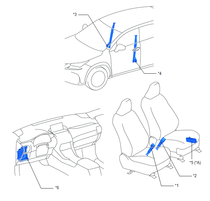
| *A | w/ Memory | - | - |
| *1 | FRONT SEAT INNER BELT ASSEMBLY RH | *2 | FRONT SEAT INNER BELT ASSEMBLY LH |
| *3 | FRONT SEAT OUTER BELT ASSEMBLY RH | *4 | FRONT SEAT OUTER BELT ASSEMBLY LH |
| *5 | FRONT POWER SEAT SWITCH LH | *6 | INSTRUMENT PANEL JUNCTION BLOCK ASSEMBLY |
System Diagram
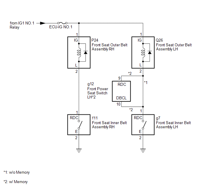
SYSTEM DIAGRAM
System Description
SYSTEM DESCRIPTION
A seat belt tension reducer has been adopted for each front seat belt. This mechanism helps reduce the belt tension applied to the occupants in the front seats when the seat belts are fastened.
Problem Symptoms Table
PROBLEM SYMPTOMS TABLE
HINT:
Use the table below to help determine the cause of problem symptoms. If multiple suspected areas are listed, the potential causes of the symptoms are listed in order of probability in the "Suspected Area" column of the table. Check each symptom by checking the suspected areas in the order they are listed. Replace parts as necessary.
Seat Belt Tension Reducer| Symptom | Suspected Area | Link |
|---|---|---|
| Driver tension reducer does not operate | ECU-IG NO.1 fuse | - |
| Front seat inner belt assembly LH | | |
| Front seat outer belt assembly LH | | |
| Harness and connector | - | |
| Front power seat control system (w/ Memory) | | |
| Front passenger tension reducer does not operate | ECU-IG NO.1 fuse | - |
| Front seat inner belt assembly RH | | |
| Front seat outer belt assembly RH | | |
| Harness and connector | - |
.gif)
READ NEXT:
 Components
COMPONENTS ILLUSTRATION *1 AIR CONDITIONING CONTROL ASSEMBLY (SEAT BELT WARNING LIGHT) *2 CENTER INSTRUMENT CLUSTER FINISH PANEL ASSEMBLY *3 COWL SIDE TRIM BOARD LH *4 DOOR SCUFF P
Removal
REMOVAL PROCEDURE 1. REMOVE MULTI-DISPLAY ASSEMBLY Click here 2. REMOVE DOOR SCUFF PLATE ASSEMBLY LH Click here 3. REMOVE COWL SIDE TRIM BOARD LH Click here 4. REMOVE REAR CONSOLE ARMREST ASS
SEE MORE:
Internal Control Module Throttle Position Performance (P060E)
MONITOR DESCRIPTION The ECM monitors the signals received from the No. 1 throttle position sensor and stop light switch assembly. As the ECM monitors the STP signal of the stop light switch assembly and the No. 1 throttle position sensor, if these signals do not correlate, this DTC is stored. DTC
CAN Communication Failure (Message Registry) (U1000)
DESCRIPTION This DTC is output when an internal malfunction of the CAN communication-related ECU is stored. DTC No. Detection Item DTC Detection Condition Trouble Area U1000 CAN Communication Failure (Message Registry) A headlight ECU sub-assembly LH CAN communication function malfu
© 2016-2026 Copyright www.lexunx.com
