Lexus NX: Low Beam Headlight Circuit
DESCRIPTION
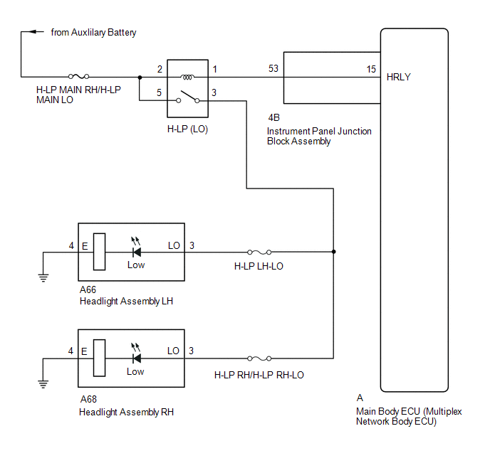
The main body ECU (multiplex network body ECU) controls the low beam headlights.
WIRING DIAGRAM
CAUTION / NOTICE / HINT
NOTICE:
- Inspect the fuses for circuits related to this system before performing the following procedure.
- Recognition code registration is necessary when replacing the main body ECU (multiplex network body ECU).
- If the main body ECU (multiplex network body ECU) is replaced, refer to Registration.
PROCEDURE
| 1. | PERFORM ACTIVE TEST USING TECHSTREAM (HEADLIGHT RELAY) |
(a) Using the Techstream, perform the Active Test.
Click here .gif)
| Tester Display | Measurement Item | Control Range | Diagnostic Note |
|---|---|---|---|
| Headlight Relay | Low beam headlight relay | ON or OFF | - |
| Tester Display |
|---|
| Headlight Relay |
OK:
Headlight relay operates. (Low beam headlights illuminate with the appropriate brightness.)
| OK | .gif) | PROCEED TO NEXT SUSPECTED AREA SHOWN IN PROBLEM SYMPTOMS TABLE |
|
.gif)
| 2. | INSPECT HEADLIGHT RELAY (H-LP [LO]) |
(a) Remove the headlight relay (H-LP [LO]) from the No. 2 engine room relay block.
(b) Inspect the headlight light relay (H-LP [LO]).
| NG | | REPLACE HEADLIGHT RELAY (H-LP [LO]) |
|
| 3. | CHECK HARNESS AND CONNECTOR (HEADLIGHT RELAY [H-LP (LO)] - BATTERY) |
| (a) Remove the headlight relay (H-LP [LO]) from the No. 2 engine room relay block. |
|
.png)
(b) Measure the voltage according to the value(s) in the table below.
Standard Voltage:
| Tester Connection | Switch Condition | Specified Condition |
|---|---|---|
| Relay terminal 5 - Body ground | Power switch off | 11 to 14 V |
| Relay terminal 2 - Body ground | Power switch off | 11 to 14 V |
| NG | | REPAIR OR REPLACE HARNESS OR CONNECTOR |
|
| 4. | CHECK HARNESS AND CONNECTOR (HEADLIGHT RELAY [H-LP (LO)] - HEADLIGHT ASSEMBLY) |
- *1: for LH
- *2: for RH
(a) Remove the headlight relay (H-LP [LO]) from the No. 2 engine room relay block.
(b) Disconnect the A66*1 and A68*2 headlight assembly connector.
(c) Measure the resistance according to the value(s) in the table below.
Standard Resistance:
for LH
| Tester Connection | Condition | Specified Condition |
|---|---|---|
| Relay terminal 3 - A66-3 (LO) | Always | Below 1 Ω |
| Headlight relay terminal 3 - Body ground | Always | 10 kΩ or higher |
for RH
| Tester Connection | Condition | Specified Condition |
|---|---|---|
| Relay terminal 3 - A68-3 (LO) | Always | Below 1 Ω |
| Headlight relay terminal 3 - Body ground | Always | 10 kΩ or higher |
| NG | | REPAIR OR REPLACE HARNESS OR CONNECTOR |
|
| 5. | CHECK HARNESS AND CONNECTOR (HEADLIGHT RELAY [H-LP (LO)] - INSTRUMENT PANEL JUNCTION BLOCK ASSEMBLY) |
(a) Remove the headlight relay (H-LP [LO]) from the No. 2 engine room relay block.
(b) Disconnect the 4B instrument panel junction block assembly connector.
(c) Measure the resistance according to the value(s) in the table below.
Standard Resistance:
| Tester Connection | Condition | Specified Condition |
|---|---|---|
| Relay terminal 1 - 4B-53 | Always | Below 1 Ω |
| Relay terminal 1 or 4B-53 - Body ground | Always | 10 kΩ or higher |
| NG | | REPAIR OR REPLACE HARNESS OR CONNECTOR |
|
| 6. | INSPECT INSTRUMENT PANEL JUNCTION BLOCK ASSEMBLY |
| (a) Remove the instrument panel junction block assembly. Click here |
|
.png)
(b) Remove the main body ECU (multiplex network body ECU) from the instrument panel junction block assembly.
Click here
(c) Measure the resistance according to the value(s) in the table below.
Standard Resistance:
| Tester Connection | Condition | Specified Condition |
|---|---|---|
| A-15 (HRLY) - 4B-53 | Always | Below 1 Ω |
| OK | | REPLACE MAIN BODY ECU (MULTIPLEX NETWORK BODY ECU) |
| NG | | REPLACE INSTRUMENT PANEL JUNCTION BLOCK ASSEMBLY |
READ NEXT:
 High Beam Headlight Circuit
DESCRIPTION The main body ECU (multiplex network body ECU) controls the high beam headlights. WIRING DIAGRAM CAUTION / NOTICE / HINT NOTICE:
Inspect the fuses for circuits related to this system b
Precaution
PRECAUTION PRECAUTION FOR REPLACEMENT (a) Always prepare a new bulb for immediate replacement. While replacing a bulb, the lens may attract dust and moisture if removed from the vehicle for a long tim
SEE MORE:
Open Circuit in Stop Light Switch Circuit (C1249)
DESCRIPTION The skid control ECU (brake booster with master cylinder assembly) receives the stop light switch assembly signal and detects the brake pedal operation status. The skid control ECU (brake booster with master cylinder assembly) has an open detection circuit, which stores this DTC if it de
Components
COMPONENTS ILLUSTRATION *A w/ Power Back Door *B w/o Power Back Door *1 BACK DOOR FINISH COVER LH *2 BACK DOOR FINISH COVER RH *3 BACK DOOR LOCK COVER *4 BACK DOOR SIDE GARNISH LH *5 BACK DOOR SIDE GARNISH RH *6 BACK DOOR TRIM BASE *7 BACK DOOR TRIM BOAR
