Lexus NX: Installation
INSTALLATION
CAUTION / NOTICE / HINT
HINT:
- Use the same procedure for the RH and LH sides.
- The procedure listed below is for the LH side.
-
A bolt without a torque specification is shown in the standard bolt chart.
Click here
.gif)
PROCEDURE
1. INSTALL AIR CONDITIONING UNIT ASSEMBLY
(a) Temporarily install the air conditioning unit assembly with the 3 bolts.
NOTICE:
To prevent damage to the installation bracket for the air conditioner unit assembly, be sure to support the air conditioner unit assembly.
2. INSTALL INSTRUMENT PANEL REINFORCEMENT ASSEMBLY WITH AIR CONDITIONING UNIT ASSEMBLY
(a) Install the instrument panel reinforcement assembly with air conditioning unit assembly with the 7 bolts and nut.
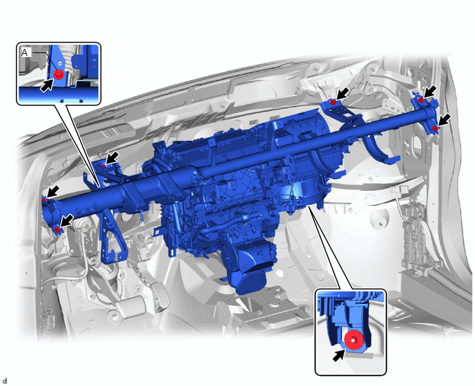
HINT:
Do not fully tighten the nut.
Torque:
Bolt A :
18 N·m {184 kgf·cm, 13 ft·lbf}
3. INSTALL AIR DUCT ASSEMBLY
(a) Install the air duct assembly with the 2 nuts.
Torque:
9.8 N·m {100 kgf·cm, 87 in·lbf}
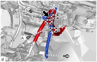
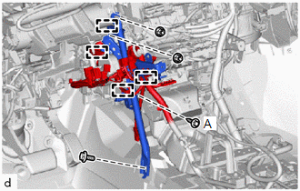
4. CONNECT INSTRUMENT PANEL WIRE
(a) Connect the instrument panel wire with the bolts.
.png)
Torque:
8.4 N·m {86 kgf·cm, 74 in·lbf}
(b) Connect the ECU integration box RH with the bolt and 2 nuts.
Torque:
8.4 N·m {86 kgf·cm, 74 in·lbf}
(c) Connect the instrument panel junction block assembly with the 2 nuts.
Torque:
8.4 N·m {86 kgf·cm, 74 in·lbf}
(d) Connect each connectors and attach each clamps.
(e) Connect the 4 ground wires with the 4 bolts.
Torque:
8.4 N·m {86 kgf·cm, 74 in·lbf}
5. INSTALL REAR NO. 1 AIR DUCT
(a) Attach the 4 claws to install the rear No. 1 air duct.
6. INSTALL NO. 2 INSTRUMENT PANEL BRACE SUB-ASSEMBLY
| (a) Install the bolt, screw, nut and No. 2 instrument panel brace sub-assembly. HINT: Do not fully tighten screw A. |
|
(b) Install the ground wire with the bolt.
Torque:
8.4 N·m {86 kgf·cm, 74 in·lbf}
(c) Attach the 3 clamps to install the wire harness.
7. INSTALL NO. 1 INSTRUMENT PANEL BRACE SUB-ASSEMBLY
| (a) Install the bolt, screw, 2 nuts and No. 1 instrument panel brace sub-assembly. HINT: Do not fully tighten screw A. |
|
(b) Attach the 4 clamps to install the wire harness.
8. INSTALL NO. 1 AIR DUCT
(a) Attach the 3 claws to install a new No. 1 air duct.
NOTICE:
If the No. 1 air duct is reused, it may fall off or abnormal noise may occur. Therefore, make sure to replace with a new one.
9. INSTALL NO. 2 AIR DUCT
(a) Attach the 3 claws to install a new No. 2 air duct.
NOTICE:
If the No. 2 air duct is reused, it may fall off or abnormal noise may occur. Therefore, make sure to replace with a new one.
(b) Attach the clamp.
10. INSTALL AIR CONDITIONING UNIT ASSEMBLY
(a) Tighten the 3 bolts, 2 screws and nut as shown in the illustration.
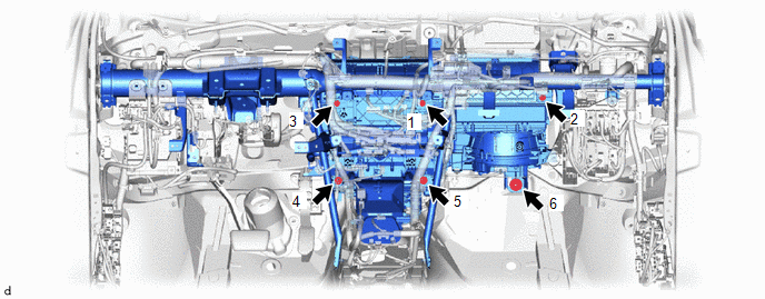
Torque:
:
9.8 N·m {100 kgf·cm, 87 in·lbf}
11. CONNECT DRAIN COOLER HOSE
| (a) Connect the drain cooler hose as shown in the illustration. NOTICE:
|
|
12. INSTALL REAR NO. 2 AIR DUCT
(a) Attach the 2 claws to install the rear No. 2 air duct.
(b) Install the clip.
13. INSTALL REAR NO. 3 AIR DUCT
(a) Attach the 2 claws to install the rear No. 3 air duct.
(b) Install the clip.
(c) Return the front floor carpet assembly to its original position with the 2 clips.
14. INSTALL FRONT SEAT ASSEMBLY LH
Click here
15. INSTALL FRONT SEAT ASSEMBLY RH
HINT:
Use the same procedure described for the LH side.
16. INSTALL LOWER DEFROSTER NOZZLE ASSEMBLY
(a) Attach the 6 claws to install the lower defroster nozzle assembly.
17. INSTALL STEERING COLUMN ASSEMBLY
(a) for Manual Tilt and Manual Telescopic Steering Column:
Click here
(b) for Power Tilt and Power Telescopic Steering Column:
Click here
18. INSTALL LOWER INSTRUMENT PANEL
Click here
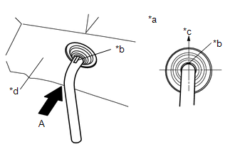
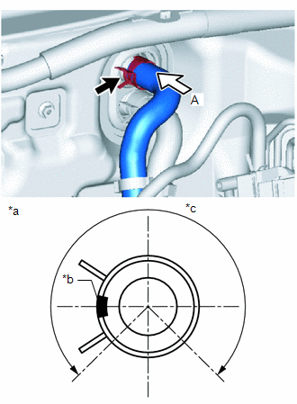
19. CONNECT WATER HOSE SUB-ASSEMBLY B
| (a) Connect the water hose sub-assembly B with the paint mark (yellow) facing left and attach the clip within the area shown in the illustration. NOTICE: Do not apply excessive force to the water hose sub-assembly B. |
|
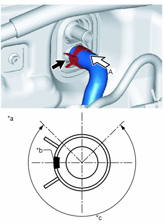
20. CONNECT HEATER WATER OUTLET HOSE A
| (a) Connect the heater water outlet hose A with the paint mark (yellow) facing left and attach the clip within the area shown in the illustration. NOTICE: Do not apply excessive force to the heater water outlet hose A. |
|
21. CONNECT AIR CONDITIONING TUBE AND ACCESSORY ASSEMBLY
(a) Remove the vinyl tape from the air conditioning tube and accessory assembly.
(b) Sufficiently apply compressor oil to 2 new O-rings and the fitting surface of the air conditioning tube and accessory assembly.
Compressor Oil:
ND-OIL 11 or equivalent
(c) Install the 2 O-rings to the air conditioner tube and accessory assembly.
NOTICE:
Keep the O-rings and O-ring fitting surfaces free of foreign matter.
(d) Connect the air conditioning tube and accessory assembly.
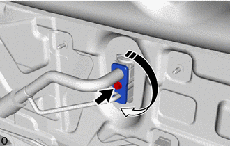
| (e) Rotate the hook connector in the direction indicated by the arrow in the illustration and install the bolt. Torque: 9.8 N·m {100 kgf·cm, 87 in·lbf} |
|
22. ADD ENGINE COOLANT
Click here
23. CHARGE AIR CONDITIONING SYSTEM WITH REFRIGERANT
Click here
24. WARM UP COMPRESSOR
Click here
25. INSPECT FOR COOLANT LEAK
Click here
26. INSPECT FOR REFRIGERANT LEAK
Click here
27. INITIALIZATION SERVO MOTOR
Click here
READ NEXT:
 Ambient Temperature Sensor
ComponentsCOMPONENTS ILLUSTRATION *1 THERMISTOR ASSEMBLY (AMBIENT TEMPERATURE SENSOR) - - RemovalREMOVAL PROCEDURE 1. REMOVE FRONT BUMPER ASSEMBLY (a) for Sport Package: Click here (b
Components
COMPONENTS ILLUSTRATION *1 BLOWER ASSEMBLY - - ILLUSTRATION *1 AIR FILTER CASE *2 AIR REFINER ELEMENT *3 BLOWER WITH FAN MOTOR SUB-ASSEMBLY *4 NO. 1 BLOWER DAMPER SERV
SEE MORE:
Air Inlet Damper Control Servo Motor Circuit (B1442)
DESCRIPTION The No. 1 blower damper servo sub-assembly sends pulse signals to inform the air conditioning amplifier assembly of the damper position. The air conditioning amplifier assembly activates the motor (normal, reverse) based on the signals to move the air inlet mode selection No. 1 blower da
Installation
INSTALLATION PROCEDURE 1. INSTALL CAMSHAFT TIMING OIL CONTROL VALVE ASSEMBLY (a) Apply a light coat of engine oil to a new O-ring and install the O-ring to the camshaft timing oil control valve assembly. NOTICE: Do not damage the O-ring when installing. HINT: An O-ring is already installed in a new
