Lexus NX: Reassembly
REASSEMBLY
PROCEDURE
1. INSTALL NO. 1 COOLER THERMISTOR
Click here .gif)
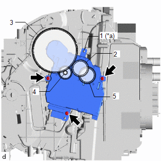
2. INSTALL NO. 1 COOLER EVAPORATOR SUB-ASSEMBLY
(a) Sufficiently apply compressor oil to 2 new O-rings and the fitting surface of the cooler expansion valve.
Compressor Oil:
ND-OIL 11 or equivalent
(b) Install the 2 O-rings to a new No. 1 cooler evaporator sub-assembly.
NOTICE:
Keep the O-rings and O-ring fitting surfaces free of foreign matter.
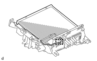
(c) Install the No. 1 cooler evaporator sub-assembly with the No. 1 cooler thermistor.
NOTICE:
When the No. 1 cooler evaporator sub-assembly is removed, make sure to install a new one. The No. 1 cooler evaporator sub-assembly cannot be reused.
| (d) Attach the clamp. |
|
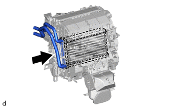
| (e) Attach the 7 guides and 10 claws to install the upper heater case. |
|
.png)
(f) Install the 2 screws.
3. INSTALL COOLER EXPANSION VALVE
| (a) Insert the cooler expansion valve. |
|
.png)
(b) Using a 4 mm hexagon wrench, install the cooler expansion valve with the 2 hexagon bolts.
Torque:
3.5 N·m {36 kgf·cm, 31 in·lbf}
(c) Install the cooling unit packing.
4. INSTALL HEATER RADIATOR UNIT SUB-ASSEMBLY
| (a) Install the heater radiator unit sub-assembly. |
|
| (b) Attach the 2 claws to install the clamp. |
|
.png)
(c) Install the screw.
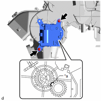
5. INSTALL NO. 1 AIR CONDITIONING RADIATOR DAMPER SERVO SUB-ASSEMBLY
| (a) Align each No. 1 air conditioning radiator damper servo sub-assembly standard position. |
|
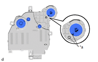
(b) Align each gear on the air conditioner radiator assembly side with the standard position as shown in the illustration.
| *a | Standard Position | - | - |
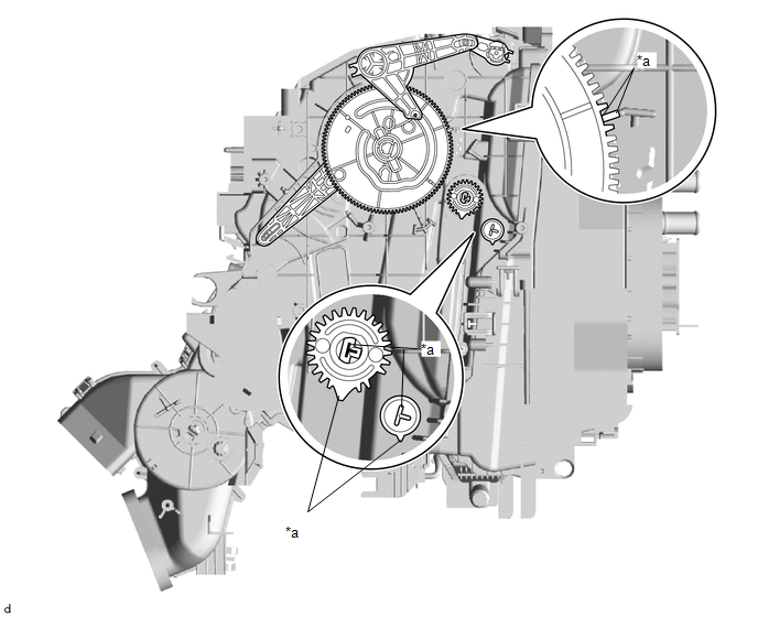
| (c) Align the positioning rib and each gear in the order shown in the illustration and temporarily install the No. 1 air conditioning radiator damper servo sub-assembly. |
|
(d) Install the No. 1 air conditioning radiator damper servo sub-assembly with the 3 screws.
6. INSTALL NO. 2 AIR CONDITIONING RADIATOR DAMPER SERVO SUB-ASSEMBLY
| (a) Align the gears with the standard position as shown in the illustration and temporarily install the No. 2 air conditioning radiator damper servo sub-assembly. |
|
(b) Install the No. 2 air conditioning radiator damper servo sub-assembly with the 2 screws.
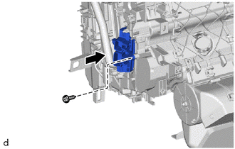
7. INSTALL QUICK HEATER ASSEMBLY
| (a) Install the quick heater assembly with the screw as shown in the illustration. |
|
8. INSTALL AIR CONDITIONING HARNESS ASSEMBLY
(a) Attach the 4 clamps to install the air conditioning harness assembly.
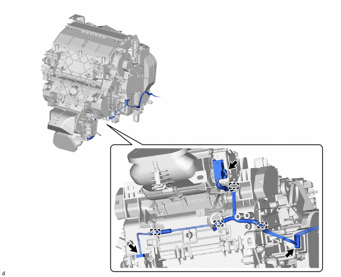
(b) Connect the 3 connectors.
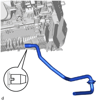
9. INSTALL DRAIN COOLER HOSE
| (a) Align the protrusion on the lower heater case with the indentation on the drain cooler hose, and install the drain cooler hose. |
|
10. INSTALL AIR CONDITIONING AMPLIFIER ASSEMBLY
| (a) Insert the guide as shown in the illustration to temporarily install the air conditioning amplifier assembly. NOTICE: Make sure to align the protrusion on the air conditioning amplifier assembly with the indentation on the air conditioning unit assembly. |
|
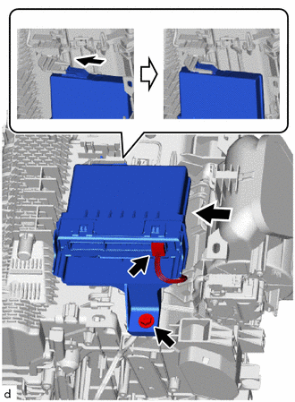
(b) Install the air conditioning amplifier assembly with the screw.
(c) Connect the air conditioning amplifier assembly connector.
11. INSTALL ASPIRATOR
| (a) Attach the 2 claws to install the aspirator. |
|
.png)
| (b) Install the aspirator hose. |
|
.png)
12. INSTALL AIR CONDITIONING RADIATOR ASSEMBLY
(a) Attach the 2 claws to install the air conditioning radiator assembly.
(b) Install the 2 screws.
(c) Attach the 3 clamps to install the air conditioning harness assembly.
(d) Connect the No. 1 blower damper servo sub-assembly connector.
READ NEXT:
 Installation
INSTALLATION CAUTION / NOTICE / HINT HINT:
Use the same procedure for the RH and LH sides.
The procedure listed below is for the LH side.
A bolt without a torque specification is shown in the s
Ambient Temperature Sensor
ComponentsCOMPONENTS ILLUSTRATION *1 THERMISTOR ASSEMBLY (AMBIENT TEMPERATURE SENSOR) - - RemovalREMOVAL PROCEDURE 1. REMOVE FRONT BUMPER ASSEMBLY (a) for Sport Package: Click here (b
SEE MORE:
Removal
REMOVAL PROCEDURE 1. REMOVE NO. 1 ENGINE UNDER COVER ASSEMBLY Click here 2. REMOVE INVERTER WITH CONVERTER ASSEMBLY Click here 3. REMOVE INVERTER WATER PUMP WITH MOTOR ASSEMBLY Click here 4. REMOVE INVERTER BRACKET ASSEMBLY Click here 5. DISCONNECT WIRE HARNESS (a) Disconnect the 4
Seat Heater for Front Left Seat does not Operate
DESCRIPTION When the seat heater switch on air conditioning control assembly is operated, the air conditioning amplifier assembly receives the signal. The air conditioning amplifier assembly receives the signal and operates the front seat heater. WIRING DIAGRAM CAUTION / NOTICE / HINT NOTICE:
If
