Lexus NX: Removal
REMOVAL
PROCEDURE
1. RECOVER REFRIGERANT FROM REFRIGERATION SYSTEM
Click here .gif)
2. REMOVE BATTERY SERVICE HOLE COVER
Click here
3. REMOVE HYBRID BATTERY SERVICE PLUG COVER
Click here
4. REMOVE SERVICE PLUG GRIP
Click here
5. CHECK TERMINAL VOLTAGE
Click here
6. REMOVE NO. 1 ENGINE UNDER COVER ASSEMBLY
Click here
7. REMOVE REAR ENGINE UNDER COVER LH
Click here
8. REMOVE REAR ENGINE UNDER COVER RH
Click here
9. DISCONNECT DISCHARGE HOSE SUB-ASSEMBLY
| (a) Remove the bolt and disconnect the discharge hose sub-assembly. |
|
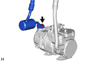
(b) Remove the O-ring from the discharge hose sub-assembly.
NOTICE:
Seal the openings of the disconnected parts using vinyl tape to prevent entry of moisture and foreign matter.
10. DISCONNECT SUCTION HOSE SUB-ASSEMBLY
| (a) Remove the bolt and disconnect the suction hose sub-assembly. |
|
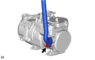
(b) Remove the O-ring from the suction hose sub-assembly.
NOTICE:
Seal the openings of the disconnected parts using vinyl tape to prevent entry of moisture and foreign matter.
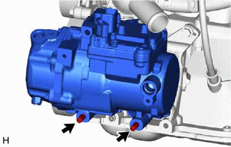
11. REMOVE COMPRESSOR ASSEMBLY WITH MOTOR
| (a) Using a screwdriver, slide the green-colored lock of connector A as shown in the illustration to release it and disconnect the connector. CAUTION: Make sure to wear insulating gloves. NOTICE:
|
|
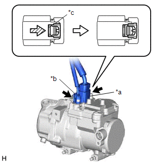
(b) Disconnect connector B.
NOTICE:
Do not allow any foreign matter or water to enter the compressor with motor assembly.
| (c) Remove the bolt and 2 nuts. |
|
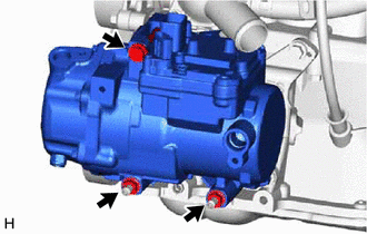
| (d) Using an E8 ''TORX'' socket wrench, remove the 2 stud bolts and the compressor assembly with motor. |
|
READ NEXT:
 Installation
INSTALLATION PROCEDURE 1. INSPECT COMPRESSOR OIL (a) When replacing the compressor assembly with motor with a new one, gradually discharge the inert gas from the service valve, and drain the follow
Components
COMPONENTS ILLUSTRATION *1 COOLER CONDENSER ASSEMBLY *2 COOLER DRYER *3 DISCHARGE HOSE SUB-ASSEMBLY *4 LIQUID PIPE SUB-ASSEMBLY *5 NO. 1 COOLER CONDENSER CUSHION *6 O-RIN
SEE MORE:
Rear Right Seat Heat Sensor Circuit (B14C2)
DESCRIPTION Power supply to the temperature sensor built into the rear seat cushion heater stops if one of the following occurs: 1) an open or short occurs in the temperature sensor circuit; or 2) the temperature sensor is damaged and its output value does not change. DTC No. Detection Item D
Blind Spot Monitor Main Switch
InspectionINSPECTION PROCEDURE 1. INSPECT COMBINATION SWITCH ASSEMBLY (BLIND SPOT MONITOR MAIN SWITCH) (a) Remove the combination switch assembly. Click here (b) Measure the resistance according to the value(s) in the table below. Standard Resistance: Tester Connection Switch Condition
