- Power Resource VB
- VL-Voltage before Boosting
- VH-Voltage after Boosting
- Boost Ratio
Lexus NX: Hybrid Battery Voltage / DC/DC Converter Voltage Correlation (P1C2D-587)
Lexus NX Service Manual / Engine & Hybrid System / 2ar-fxe (hybrid / Battery Control) / Hybrid Control System / Hybrid Battery Voltage / DC/DC Converter Voltage Correlation (P1C2D-587)
DTC SUMMARY
MALFUNCTION DESCRIPTION
The hybrid vehicle control ECU detects a VB sensor or VL sensor malfunction.
The cause of this malfunction may be one of the following:
Inside of inverter voltage sensor circuit malfunction
- Voltage sensor malfunction
- Motor generator control ECU (MG ECU) malfunction
- Communication (wire harness) malfunction
High voltage system malfunction
- HV battery malfunction
- Hybrid battery junction block assembly malfunction
- Inverter with converter assembly malfunction
- High-voltage wire harness malfunction
- High-voltage connector or connection malfunction
Inspection Overview
| Inspection Content | Reason (Narrow Down in Order Using Inspection Procedures Below) | Inspection Step |
|---|---|---|
| Check for DTCs (HV) | Output DTCs | 1 |
| Check for DTCs (check voltage sensor malfunction locations) Check for DTCs (drive test) | Put vehicle in ready ON (vehicle stopped or being driven) and then check whether DTCs are output again. | 3, 4 |
| Read value using Techstream | Data List value | 5 |
| Check freeze frame data (HV) | FREEZE FRAME DATA | 6, 7 |
| Read value using Techstream | Accelerator and brake pedal simultaneously depressed Data List value | 8 |
DESCRIPTION
For a description of the boost converter.
Click here .gif)
The MG ECU uses a voltage sensor (VL) that is built into the boost converter to detect the high voltage before it is boosted. The ECU also uses the battery voltage sensor to detect HV battery voltage (VB).
HINT:
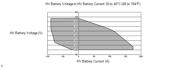
Using the Techstream, check the Data List values of "Power Resource VB" and "Batt Pack Current Val". If these values are not within the range below, there is a malfunction in the battery voltage sensor circuit.
| DTC No. | Detection Item | DTC Detection Condition | Trouble Area | MIL | Warning Indicate |
|---|---|---|---|---|---|
| P1C2D-587 | Hybrid Battery Voltage / DC/DC Converter Voltage Correlation | Voltages from HV battery voltage (VB) sensor and boost converter voltage (VL) sensor deviate: Difference between "VL-Voltage before Boosting" and "Power Resource VB" is large when the boosting request is given. (1 trip detection logic) |
| Comes on | Master Warning Light: Comes on |
| DTC No. | Data List |
|---|---|
| P1C2D-587 | |
MONITOR DESCRIPTION
The hybrid vehicle control ECU monitors signals of HV battery voltage (VB) and boost converter voltage (VL) sensors. When a large difference occurs between the voltages from the VB and VL sensors, the hybrid vehicle control ECU interprets this as a failure of either of the sensors. The hybrid vehicle control ECU will illuminate the MIL and store a DTC.
MONITOR STRATEGY
| Related DTCs | P1C2D (INF 587): Voltage (VB or VL) sensor deviation |
| Required sensors/components | Boost converter |
| Frequency of operation | - |
| Duration | TMC's intellectual property |
| MIL operation | 1 driving cycle |
| Sequence of operation | None |
TYPICAL ENABLING CONDITIONS
| The monitor will run whenever the following DTCs are not stored | TMC's intellectual property |
| Other conditions belong to TMC's intellectual property | - |
TYPICAL MALFUNCTION THRESHOLDS
| TMC's intellectual property | - |
COMPONENT OPERATING RANGE
| Hybrid vehicle control ECU | DTC P1C2D (INF 587) is not detected |
CONFIRMATION DRIVING PATTERN
- Connect the Techstream to the DLC3.
- Turn the power switch on (IG) and turn the Techstream on.
- Clear the DTCs (even if no DTCs are stored, perform the clear DTC procedure).
- Turn the power switch off and wait for 30 seconds or more.
- Turn the power switch on (IG) and turn the Techstream on.
- Turn the power switch on (READY).
- With the shift lever in D, depress both the accelerator pedal and brake pedal at the same time to raise the SOC to a sufficient level.
- Move the shift lever to P, check that the engine is stopped and move the shift lever to N.
- Set the A/C for maximum cooling.
- Leave the vehicle for a few minutes.
- Enter the following menus: Powertrain / Hybrid Control / Trouble Codes.
-
Read the current DTCs.
HINT:
- If a current DTC is output, the system is malfunctioning.
- If current DTCs are not output, perform the following steps to check for permanent DTCs.
- Check that the permanent DTCs are cleared.
- If the permanent DTCs are not cleared, perform the universal trip, and then check for permanent DTCs again.
CAUTION / NOTICE / HINT
HINT:
When the accelerator pedal is not depressed with the power switch on (READY) and the shift lever in P, if "VL-Voltage before Boosting" and the "Power Resource VB" is approximately same after repair, the condition is judged as normal.
PROCEDURE
| 1. | CHECK DTC OUTPUT (HYBRID CONTROL) |
(a) Connect the Techstream to the DLC3.
(b) Turn the power switch on (IG).
(c) Enter the following menus: Powertrain / Hybrid Control / Trouble Codes.
(d) Check for DTCs.
Powertrain > Hybrid Control > Trouble Codes| Result | Proceed to |
|---|---|
| One of the following applies:
| A |
| P1C2D and P0CA3-442 (voltage execution value malfunction) are output at the same time. | B |
| DTC indicated in Chart 1 is output at the same time. | C |
| DTC indicated in Chart 2 is output at the same time. | D |
Table 1:
| Malfunction Content | Relevant DTC | |
|---|---|---|
| Microcomputer malfunction | P0A1A-151, 658 | Generator Control Module |
| P0A1B-786 | Drive Motor "A" Control Module | |
| P0A1D-148 | Hybrid Powertrain Control Module | |
| P1C2A-155 | Generator A/D Converter Circuit | |
| P1CA6-156 | Generator Control Module Malfunction | |
| P1CA7-193 | Drive Motor Control Module Malfunction | |
| P2511-149 | HV CPU Power Relay Sense Circuit Intermittent No Continuity | |
| P3133-659 | Communication Error from Generator to Drive Motor "A" | |
| P3134-661 | Communication Error from Drive Motor "A" to Generator | |
| P324E-788 | MG-ECU Power Relay Intermittent Circuit | |
| Power source circuit malfunction | P06E6-164 | Sensor Power Supply "C" Circuit / Open |
| P1C73-512 | Sensor Standard Voltage "F" Circuit / Open | |
| Communication system malfunction | U0110 (all INF codes)*1 | Lost Communication with Drive Motor Control Module "A" |
| Sensor and actuator circuit malfunction | P0B23-129 | Hybrid Battery "A" Voltage |
| System malfunction | P0D2F-266 | Drive Motor "A" Inverter Voltage Sensor Circuit Low |
| P0D30-267 | Drive Motor "A" Inverter Voltage Sensor Circuit High | |
| P0E32-585 | DC/DC Converter Voltage Sensor "A" Range / Performance | |
| P0E33-589 | DC/DC Converter Voltage Sensor "A" Low | |
| P0E34-590 | DC/DC Converter Voltage Sensor "A" High | |
| P3004-132 | High Voltage Power Resource | |
Table 2:
| Malfunction Content | Relevant DTC | |
|---|---|---|
| Microcomputer malfunction | P0AFC-123 | Hybrid Battery Pack Sensor Module |
| Sensor and actuator circuit malfunction | P0B3D-123 | Hybrid Battery Voltage Sensor "A" Circuit Low |
| P0B42-123 | Hybrid Battery Voltage Sensor "B" Circuit Low | |
| P0B47-123 | Hybrid Battery Voltage Sensor "C" Circuit Low | |
| P0B4C-123 | Hybrid Battery Voltage Sensor "D" Circuit Low | |
| P0B51-123 | Hybrid Battery Voltage Sensor "E" Circuit Low | |
| P0B56-123 | Hybrid Battery Voltage Sensor "F" Circuit Low | |
| P0B5B-123 | Hybrid Battery Voltage Sensor "G" Circuit Low | |
| P0B60-123 | Hybrid Battery Voltage Sensor "H" Circuit Low | |
| P0B65-123 | Hybrid Battery Voltage Sensor "I" Circuit Low | |
| P0B6A-123 | Hybrid Battery Voltage Sensor "J" Circuit Low | |
| P0B6F-123 | Hybrid Battery Voltage Sensor "K" Circuit Low | |
| P0B74-123 | Hybrid Battery Voltage Sensor "L" Circuit Low | |
| P0B79-123 | Hybrid Battery Voltage Sensor "M" Circuit Low | |
| P0B7E-123 | Hybrid Battery Voltage Sensor "N" Circuit Low | |
| P0B83-123 | Hybrid Battery Voltage Sensor "O" Circuit Low | |
| P0B88-123 | Hybrid Battery Voltage Sensor "P" Circuit Low | |
| P0B8D-123 | Hybrid Battery Voltage Sensor "Q" Circuit Low | |
| P0B92-123 | Hybrid Battery Voltage Sensor "R" Circuit Low | |
| P308A-123 | Hybrid Battery Voltage Sensor All Circuits Low | |
HINT:
- *1: If any INF codes are output for this DTC, refer to the corresponding diagnostic procedure.
-
P1C2D-587 may be output as a result of the malfunction indicated by the DTCs above.
- The chart above is listed in inspection order of priority.
- Check DTCs that are output at the same time by following the listed order. (The main cause of the malfunction can be determined without performing unnecessary inspections.)
(e) Turn the power switch off.
| B | .gif) | REPLACE INVERTER WITH CONVERTER ASSEMBLY |
| C | | GO TO DTC CHART (HYBRID CONTROL SYSTEM) |
| D | | GO TO DTC CHART (HYBRID BATTERY SYSTEM) |
|
.gif)
| 2. | CLEAR DTC |
Click here
|
| 3. | CHECK DTC OUTPUT (CHECK FAILURE PART) |
(a) Apply the parking brake and secure the wheels using chocks.
(b) Connect the Techstream to the DLC3. *1
(c) Turn the power switch on (READY). *2
(d) Enter the following menus: Powertrain / Hybrid Control / Data List. *3
Powertrain > Hybrid Control > Data List| Tester Display |
|---|
| Power Resource VB |
| VL-Voltage before Boosting |
| Batt Pack Current Val |
(e) If both "Power Resource VB" and "VL-Voltage before Boosting" are less than 280 V, move the shift lever to D and depress both the accelerator pedal and brake pedal at the same time to raise both values to 280 V or more. *4
(f) Move the shift lever to P. *5
(g) Set the air conditioning to MAX COOL and turn the headlights on. *6
(h) Confirm that "Batt Pack Current Val" is more than 3 A. *7
(i) With the engine stopped and the conditions of steps *5, *6 and *7 satisfied, leave the vehicle for 15 seconds. *8
(j) Enter the following menus: Powertrain / Hybrid Control / Trouble codes. *9
(k) Check for DTCs. *10
Powertrain > Hybrid Control > Trouble CodesNOTICE:
If the low HV battery information comes on, move the shift lever to P and start the engine to charge the HV battery. After the engine stops, perform steps *1 through *10 again.
| Result | Proceed to |
|---|---|
| No DTCs are output, or DTCs except the following are output. | A |
| P0B23-129 (Hybrid Battery "A" Voltage) is output. | B |
| P0E32-585 (DC/DC Converter Voltage Sensor "A" Range / Performance) is output. | C |
| P3000-388 (Battery Control System) is output. | D |
| P3004-132 (High Voltage Power Resource) is output. | E |
(l) Turn the power switch off.
| B | | REPLACE BATTERY VOLTAGE SENSOR |
| C | | REPLACE INVERTER WITH CONVERTER ASSEMBLY |
| D | | LEAVE VEHICLE WITH THE SHIFT LEVER IN P, AND CHARGE HV BATTERY BY IDLING UNTIL IDLING STOPS (PERFORM STEPS *1 THROUGH *10) |
| E | | REPLACE BATTERY VOLTAGE SENSOR |
|
| 4. | CHECK DTC OUTPUT (ROAD TEST) |
(a) Turn the power switch on (READY). *11
(b) Perform a road test that repeats full acceleration to 60 km/h (37 mph) and then braking to a complete stop three times. *12
CAUTION:
Perform this road test only in an appropriate safe location, in accordance with all local laws.
(c) Connect the Techstream to the DLC3. *13
(d) Enter the following menus: Powertrain / Hybrid Control / Trouble Codes. *14
(e) Check for DTCs. *15
Powertrain > Hybrid Control > Trouble Codes| Result | Proceed to |
|---|---|
| No DTCs are output, or DTCs except the following are output. | A |
| P0B23-129 (Hybrid Battery "A" Voltage) is output. | B |
| P0E32-585 (DC/DC Converter Voltage Sensor "A" Range / Performance) is output. | C |
| P3000-388 (Battery Control System) is output. | D |
| P3004-132 (High Voltage Power Resource) is output. | E |
(f) Turn the power switch off.
| B | | REPLACE BATTERY VOLTAGE SENSOR |
| C | | REPLACE INVERTER WITH CONVERTER ASSEMBLY |
| D | | LEAVE VEHICLE WITH THE SHIFT LEVER IN P, AND CHARGE HV BATTERY BY IDLING UNTIL IDLING STOPS (PERFORM STEPS *11 THROUGH *15) |
| E | | REPLACE BATTERY VOLTAGE SENSOR |
|
| 5. | READ VALUE USING TECHSTREAM (DATA LIST) |
(a) Apply the parking brake and secure the wheels using chocks.
(b) Connect the Techstream to the DLC3.
(c) Turn the power switch on (READY).
(d) Enter the following menus: Powertrain / Hybrid Control / Data List / Power Resource VB, VL-Voltage before Boosting, VH-Voltage after Boosting.
Powertrain > Hybrid Control > Data List| Tester Display |
|---|
| Power Resource VB |
| VL-Voltage before Boosting |
| VH-Voltage after Boosting |
(e) If both "Power Resource VB" and "VL-Voltage before Boosting" are less than 280 V, move the shift lever to D and depress both the accelerator pedal and brake pedal at the same time to raise both values to 280 V or more.
(f) Turn the engine off, move the shift lever to P, and read the Data List with the vehicle stationary.
| Result | Proceed to |
|---|---|
| Both of the following are not satisfied. | A |
| Both of the following are satisfied:
| B |
| Both of the following are satisfied:
| C |
(g) Turn the power switch off.
| B | | REPLACE INVERTER WITH CONVERTER ASSEMBLY |
| C | | REPLACE BATTERY VOLTAGE SENSOR |
|
| 6. | CHECK FREEZE FRAME DATA (HYBRID CONTROL) |
(a) Connect the Techstream to the DLC3.
(b) Turn the power switch on (IG).
(c) Enter the following menus: Powertrain / Hybrid Control / Trouble Codes.
(d) Read the freeze frame data of DTC P1C2D-587.
| Result | Proceed to |
|---|---|
| Both of the following are satisfied or both of the following are not satisfied. | A |
| "Power Resource VB" is less than 204 V or more than 340 V. | B |
| "VL-Voltage before Boosting" is less than 204 V or more than 340 V. | C |
(e) Turn the power switch off.
| B | | REPLACE BATTERY VOLTAGE SENSOR |
| C | | REPLACE INVERTER WITH CONVERTER ASSEMBLY |
|
| 7. | CHECK FREEZE FRAME DATA (HYBRID CONTROL) |
(a) Connect the Techstream to the DLC3.
(b) Turn the power switch on (IG).
(c) Enter the following menus: Powertrain / Hybrid Control / Trouble Codes.
(d) Read the freeze frame data of DTC P1C2D-587.
HINT:
In the freeze frame data, read the item "Power Resource VB" and all of the "Battery Block Vol".
| Result | Proceed to |
|---|---|
| Freeze frame data is not stored. | A |
| Both of the following are satisfied:
| B |
| Neither A nor B is satisfied. | C |
(e) Turn the power switch off.
| B | | REPLACE INVERTER WITH CONVERTER ASSEMBLY |
| C | | REPLACE BATTERY VOLTAGE SENSOR |
|
| 8. | READ VALUE USING TECHSTREAM (DATA LIST) |
(a) Apply the parking brake and secure the wheels using chocks.
(b) Connect the Techstream to the DLC3.
(c) Turn the power switch on (READY).
(d) Enter the following menus: Powertrain / Hybrid Control / Data List.
(e) If both "Power Resource VB" and "VL-Voltage before Boosting" are less than 280 V, move the shift lever to D and depress both the accelerator pedal and brake pedal at the same time to raise both values to 280 V or more.
Powertrain > Hybrid Control > Data List| Tester Display |
|---|
| Power Resource VB |
| VL-Voltage before Boosting |
(f) Turn the engine off, move the shift lever to P, and read the "Power Resource VB" and all of the "Battery Block Vol", with the vehicle is stationary.
Powertrain > Hybrid Control > Data List| Tester Display |
|---|
| Power Resource VB |
| Battery Block Vol -V01 |
| Battery Block Vol -V02 |
| Battery Block Vol -V03 |
| Battery Block Vol -V04 |
| Battery Block Vol -V05 |
| Battery Block Vol -V06 |
| Battery Block Vol -V07 |
| Battery Block Vol -V08 |
| Battery Block Vol -V09 |
| Battery Block Vol -V10 |
| Battery Block Vol -V11 |
| Battery Block Vol -V12 |
| Battery Block Vol -V13 |
| Battery Block Vol -V14 |
| Battery Block Vol -V15 |
| Battery Block Vol -V16 |
| Battery Block Vol -V17 |
| Result | Proceed to |
|---|---|
| Both of the following are satisfied:
| A |
| The preceding condition is not satisfied. | B |
(g) Turn the power switch off.
| A | | REPLACE INVERTER WITH CONVERTER ASSEMBLY |
| B | | REPLACE BATTERY VOLTAGE SENSOR |
READ NEXT:
 Generator Position Sensor Angle Malfunction (P1CAC-200,P1CAF-792,P1CB2-793)
DESCRIPTION The MG ECU, which is built into the inverter with converter assembly, monitors its internal operation and detects the following malfunctions. DTC No. Detection Item DTC Detection Co
Drive Motor "A" Position Sensor Angle Malfunction (P1CAD-168,P1CB0-795,P1CB3-796)
DESCRIPTION The MG ECU, which is built into the inverter with converter assembly, monitors its internal operation and detects malfunctions. HINT: The term "drive motor A" indicates the motor (MG2).
Drive Motor "B" Position Sensor Angle Malfunction (P1CAE-715,P1CB1-798,P1CB4-799)
DESCRIPTION The inverter with converter assembly (MG ECU) monitors its internal operation and detects malfunctions. DTC No. Detection Item DTC Detection Condition Trouble Area MIL Warning
SEE MORE:
Problem Symptoms Table
PROBLEM SYMPTOMS TABLE HINT:
Use the table below to help determine the cause of problem symptoms. If multiple suspected areas are listed, the potential causes of the symptoms are listed in order of probability in the "Suspected Area" column of the table.
Check each system by checking the suspec
Reassembly
REASSEMBLY PROCEDURE 1. INSTALL NO. 2 MOULDING TAPE HINT:
When installing the No. 2 moulding tape, heat the front bumper cover and No. 2 moulding tape using a heat light.
Use the same procedure described for the other side.
Standard: Item Temperature Front Bumper Cover 20 to 30°
© 2016-2026 Copyright www.lexunx.com
