Lexus NX: Removal
REMOVAL
PROCEDURE
1. REMOVE CONSOLE ARMREST ASSEMBLY (for Front Side)
Click here .gif)
2. REMOVE UPPER NO. 2 CONSOLE PANEL GARNISH (for Front Side)
Click here
3. REMOVE DOOR SCUFF PLATE ASSEMBLY LH (for Front Side)
Click here
4. REMOVE COWL SIDE TRIM BOARD LH (for Front Side)
Click here
5. REMOVE INSTRUMENT SIDE PANEL LH (for Front Side)
Click here
6. REMOVE NO. 1 INSTRUMENT PANEL SAFETY PAD SUB-ASSEMBLY (for Front Side)
Click here
7. REMOVE NO. 1 INSTRUMENT PANEL UNDER COVER SUB-ASSEMBLY (for Front Side)
Click here
8. REMOVE LOWER NO. 1 INSTRUMENT PANEL FINISH PANEL (for Front Side)
Click here
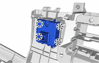
9. REMOVE NO. 1 FOLD SEAT SWITCH ASSEMBLY (for Front Side)
| (a) Detach the 4 claws to remove the No. 1 fold seat switch assembly. |
|
10. REMOVE BENCH TYPE REAR SEAT CUSHION ASSEMBLY (for Rear Seat)
Click here
11. REMOVE NO. 3 BATTERY SERVICE COVER BOARD (for Rear Seat)
Click here
12. REMOVE NO. 2 BATTERY SERVICE COVER BOARD (for Rear Seat)
Click here
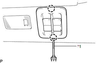
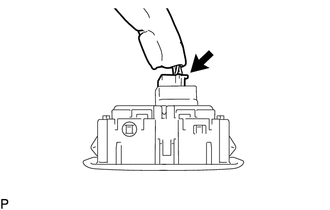
13. REMOVE REAR POWER SEAT SWITCH (for Rear Seat)
HINT:
Use the same procedure for both rear power seat switches.
| (a) Detach the 2 claws to remove the rear power seat switch. |
|
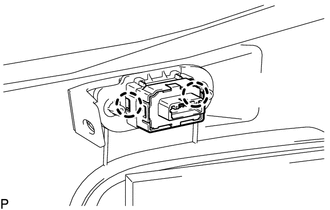
14. REMOVE NO. 2 FOLD SEAT SWITCH ASSEMBLY (for Rear Side)
| (a) Using a screwdriver, detach the 2 claws. HINT: Tape the screwdriver tip before use. |
|
| (b) Disconnect the connector to remove the No. 2 fold seat switch assembly. |
|
READ NEXT:
 Inspection
INSPECTION PROCEDURE 1. INSPECT NO. 1 FOLD SEAT SWITCH ASSEMBLY (for Front Side) (a) Measure the resistance according to the value(s) in the table below. Standard Resistance: Tester Connection
Installation
INSTALLATION PROCEDURE 1. INSTALL NO. 2 FOLD SEAT SWITCH ASSEMBLY (for Rear Side) (a) Connect the connector. (b) Attach the 2 claws to install the No. 2 fold seat switch assembly.
SEE MORE:
Precaution
PRECAUTION PRECAUTION FOR DISCONNECTING CABLE FROM NEGATIVE AUXILIARY BATTERY TERMINAL NOTICE: When disconnecting and reconnecting the auxiliary battery. Click here HINT: When disconnecting and reconnecting the auxiliary battery, there is an automatic learning function that completes learning when
Noise Occurs
PROCEDURE 1. CHECK NOISE CONDITION (a) Check from which direction the noise comes (front left or right, or rear left or right). OK: The location of the noise source can be determined. NG GO TO STEP 3
OK 2. CHECK SPEAKERS (a) Check the installation condi
