Lexus NX: Removal
REMOVAL
PROCEDURE
1. REMOVE REAR SEAT ASSEMBLY (for Manual Seat)
Click here .gif)
2. REMOVE REAR SEAT ASSEMBLY (for Power Seat)
Click here
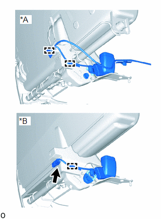
3. REMOVE REAR SEAT INNER WITH CENTER BELT ASSEMBLY RH
| (a) for Manual Seat: (1) w/o Seat Heater System:
(2) w/ Seat Heater System:
|
|
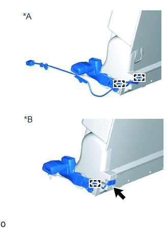
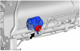
(b) for Power Seat:
| (1) Disconnect the connector. |
|
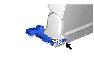
(2) Using a clip remover, detach the wire harness clamp.
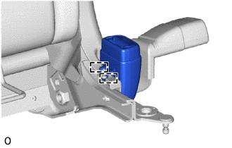
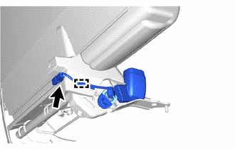
| (c) Remove the bolt. |
|
| (d) Detach the 2 hooks and remove the rear seat inner with center belt assembly RH. |
|
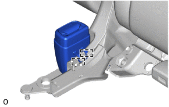
4. REMOVE REAR SEAT INNER BELT ASSEMBLY LH
| (a) for Manual Seat: (1) w/o Seat Heater System:
(2) w/ Seat Heater System:
|
|
(b) for Power Seat:
| (1) Disconnect the connector. |
|
(2) Using a clip remover, detach the wire harness clamp.
| (c) Remove the bolt. |
|
| (d) Detach the 2 hooks and remove the rear seat inner belt assembly LH. |
|
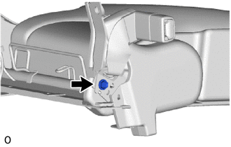
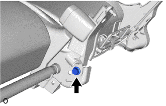
5. REMOVE REAR SEAT CENTER LAP TYPE BELT ASSEMBLY LH
| (a) Remove the nut. |
|
(b) Remove the rear seat center lap type belt assembly LH from the rear seat belt holder.
READ NEXT:
 Inspection
INSPECTION PROCEDURE 1. INSPECT REAR SEAT INNER WITH CENTER BELT ASSEMBLY RH (a) for Manual Seat: (1) w/o Seat Heater System: Measure the resistance according to the value(s) in the table below. St
Installation
INSTALLATION PROCEDURE 1. INSTALL REAR SEAT CENTER LAP TYPE BELT ASSEMBLY LH (a) Install the rear seat center lap type belt assembly LH with the nut. Torque: 42 N·m {428 kgf·cm, 31 ft·lbf} NOTI
SEE MORE:
Installation
INSTALLATION PROCEDURE 1. INSTALL NO. 3 INDOOR ELECTRICAL KEY ANTENNA ASSEMBLY NOTICE: Do not reuse dropped or damaged parts. (a) Connect the connector. (b) Attach the clamp to install the No. 3 indoor electrical key antenna assembly. 2. INSTALL NO. 2 TOOL BOX SUB-ASSEMBLY Click here 3. INSTALL
Refrigerant Line
ComponentsCOMPONENTS ILLUSTRATION *1 LIQUID TUBE SUB-ASSEMBLY *2 DISCHARGE HOSE SUB-ASSEMBLY *3 SUCTION HOSE SUB-ASSEMBLY *4 AIR CONDITIONER TUBE AND ACCESSORY ASSEMBLY *5 PIPING CLAMP *6 O-RING N*m (kgf*cm, ft.*lbf): Specified torque ● Non-reusable part
