Lexus NX: Steering Pad Switch Circuit
DESCRIPTION
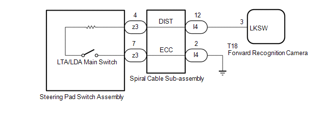
The forward recognition camera receives the LTA/LDA main switch on/off signal from the steering pad switch assembly.
WIRING DIAGRAM
CAUTION / NOTICE / HINT
NOTICE:
During the steering pad switch assembly check, check the precautions for the airbag system since the horn button assembly is removed during servicing (installation/removal of parts, checks, replacement, etc.).
Click here .gif)
PROCEDURE
| 1. | READ VALUE USING TECHSTREAM |
(a) Connect the Techstream to the DLC3.
(b) Turn the power switch on (IG).
(c) Turn the Techstream on.
(d) Enter the following menus: Chassis / Lane Control / Data List.
Chassis > Lane Control > Data List| Tester Display | Measurement Item | Range | Normal Condition | Diagnostic Note |
|---|---|---|---|---|
| LDA Control | A lane tracing assist system shows whether possibility is in control state | Permission / suppression | Prohibition: A lane tracing assistant player is impossible of system control Permission: Lane tracing assist system control is possible | - |
| Tester Display |
|---|
| LDA Control |
(e) Read the Data List according to the display on the Techstream.
| Result | Proceed to |
|---|---|
| The value of each Data List item changes according to the operation of the LTA/LDA main switch. | A |
| The value of each Data List item does not change according to the operation of the LTA/LDA main switch. | B |
| A | .gif) | TO THE NEXT CHECK CIRCUIT SHOWN IN THE PROBREM SYMPTOMS TABLE |
|
.gif)
| 2. | INSPECT STEERING PAD SWITCH ASSEMBLY |
(a) Remove the steering pad switch assembly.
Click here
(b) Inspect the steering pad switch assembly.
Click here
| NG | | REPLACE STEERING PAD SWITCH ASSEMBLY |
|
| 3. | INSPECT SPIRAL CABLE SUB-ASSEMBLY |
(a) Remove the spiral cable sub-assembly.
Click here
(b) Inspect the spiral cable sub-assembly.
Click here
| NG | | REPLACE SPIRAL CABLE SUB-ASSEMBLY |
|
| 4. | CHECK HARNESS AND CONNECTOR (SPIRAL CABLE SUB-ASSEMBLY - FORWARD RECOGNITION CAMERA) |
(a) Disconnect the I4 spiral cable sub-assembly connector.
(b) Disconnect the T18 forward recognition camera connector.
(c) Measure the resistance according to the value(s) in the table below.
Standard Resistance:
| Tester Connection | Condition | Specified Condition |
|---|---|---|
| I4-12 (DIST) - T18-3 (LKSW) | Always | Below 1 Ω |
| I4-12 (DIST) or T18-3 (LKSW) - Body Ground | Always | 10 kΩ higher |
(d) Connect the I4 spiral cable sub-assembly connector.
(e) Connect the T18 forward recognition camera connector.
| NG | | REPAIR OR REPLACE HARNESS OR CONNECTOR |
|
| 5. | CHECK HARNESS AND CONNECTOR (SPIRAL CABLE SUB-ASSEMBLY - BODY GROUND) |
(a) Disconnect the spiral cable sub-assembly connector.
(b) Measure the resistance according to the value(s) in the table below.
Standard Resistance:
| Tester Connection | Condition | Specified Condition |
|---|---|---|
| I4-2 (ECC) - Body ground | Always | Below 1 Ω |
(c) Connect the spiral cable sub-assembly connector.
| OK | | PROCEED TO NEXT SUSPECTED AREA SHOWN IN PROBLEM SYMPTOMS TABLE |
| NG | | REPAIR OR REPLACE HARNESS OR CONNECTOR |
READ NEXT:
 Indicator Circuit
DESCRIPTION The LTA/LDA indicator output request signal is sent from the forward recognition camera to the combination meter assembly via CAN communication. CAUTION / NOTICE / HINT NOTICE:
When rep
Removal
REMOVAL PROCEDURE 1. REMOVE FRONT BUMPER ASSEMBLY (a) for Sport Package: Click here (b) except Sport Package: Click here 2. REMOVE MILLIMETER WAVE RADAR SENSOR ASSEMBLY NOTICE: Do not reuse the mi
SEE MORE:
Installation
INSTALLATION CAUTION / NOTICE / HINT HINT: Perform "Inspection After Repairs" after replacing the cylinder head sub-assembly. Click here PROCEDURE 1. INSTALL CYLINDER HEAD GASKET (a) Clean the cylinder block and cylinder head sub-assembly with solvent. (b) Apply a seal packing to a new cylinder he
Inspection
INSPECTION PROCEDURE 1. INSPECT QUICK HEATER ASSEMBLY (a) Measure the resistance according to the value(s) in the table below. Standard Resistance: Tester Connection Condition Specified Condition A-1 (B) - B-1 (E) Always Below 1 Ω A-2 (E) - B-2 (B) Always Below 1 Ω A
