Lexus NX: Terminals Of Ecu
TERMINALS OF ECU
CHECK INSTRUMENT PANEL JUNCTION BLOCK ASSEMBLY AND MAIN BODY ECU (MULTIPLEX NETWORK BODY ECU)
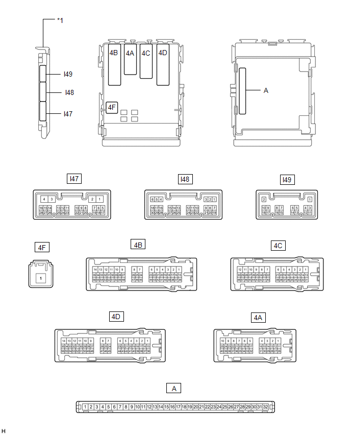
| *1 | Main Body ECU (Multiplex Network Body ECU) | - | - |
(a) Measure the voltage and check for pulses according to the value(s) in the table below.
| Terminal No. (Symbol) | Wiring Color | Terminal Description | Condition | Specified Condition |
|---|---|---|---|---|
| I48-1 (DIM) - Body ground | L - Body ground | High beam headlight drive output | Power switch off | Below 1 V |
| Power switch on (IG) | 11 to 14 V | |||
| I48-8 (A) - Body ground | G - Body ground | Light control switch Auto position signal input | Light control switch in Auto position | Below 1 V |
| Light control switch not in Auto position | 11 to 14 V | |||
| I48-23 (AHBI) - Body ground | P - Body ground | Combination switch assembly (automatic high beam main switch) signal input | Combination switch assembly (automatic high beam main switch) on | Below 1 V |
| Combination switch assembly (automatic high beam main switch) off | 11 to 14 V | |||
| I48-24 (HU) - Body ground | Y - Body ground | Headlight dimmer switch high position signal input | Headlight dimmer switch in high position | Below 1 V |
| Headlight dimmer switch not in high position | 11 to 14 V | |||
| I48-19 (CLTB) - I48-21 (CLTE) | W - V | Automatic light control sensor power supply output | Power switch off | Below 1 V |
| Power switch on (IG) | 11 to 14 V | |||
| I48-20 (CLTS) - Body ground | P - Body ground | Automatic light control sensor signal input | Power switch off | Below 1 V |
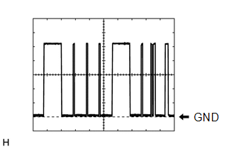
| Automatic light control system operating | Pulse generation (See waveform 1) |
(b) Waveform 1
| Item | Content |
|---|---|
| Terminal No. (Symbol) | I48-20 (CLTS) - Body ground |
| Tool Setting | 2 V/DIV., 10 ms./DIV. |
| Condition | Automatic light control system operating |
HINT:
The communication waveform changes according to the surrounding brightness.
CHECK FORWARD RECOGNITION CAMERA
Click here .gif)
READ NEXT:
 Diagnosis System
DIAGNOSIS SYSTEM DESCRIPTION (a) Automatic high beam system data and Diagnostic Trouble Codes (DTCs) can be read from the Data Link Connector 3 (DLC3) of the vehicle. When the system seems to be malfu
Dtc Check / Clear
DTC CHECK / CLEAR CHECK DTC (a) Connect the Techstream to the DLC3. (b) Turn the power switch on (IG). (c) Turn the Techstream on. (d) Enter the following menus: Body Electrical / Main Body / Trouble
Fail-safe Chart
FAIL-SAFE CHART AUTOMATIC HIGH BEAM SYSTEM (a) The main body ECU (multiplex network body ECU) operates in fail-safe mode if an abnormal condition such as those listed below has been detected. Item
SEE MORE:
Installation
INSTALLATION CAUTION / NOTICE / HINT HINT:
Use the same procedure for the RH and LH sides.
The procedure described below is for the LH side.
PROCEDURE 1. INSTALL SIDE TURN SIGNAL LIGHT ASSEMBLY LH (a) Connect the connector. (b) Align the side turn signal light assembly LH with the alignment
Reassembly
REASSEMBLY CAUTION / NOTICE / HINT NOTICE: Do not allow any dirt (fingerprints, grease, etc.) to adhere to the meter glass. If the glass is dirty, wipe it clean with a soft cloth. PROCEDURE 1. INSTALL COMBINATION METER GLASS (a) Attach the 8 claws to install the combination meter glass.
