Lexus NX: Pattern Select Switch EV Mode Circuit
DESCRIPTION
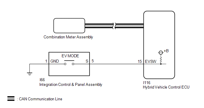
The EV drive mode signal will be sent to the hybrid vehicle control ECU when the EV drive mode switch (integration control & panel assembly) is operated. If the specified conditions are met, the system enters EV drive mode and the vehicle will be driven using EV drive mode. This signal is then transmitted from the hybrid vehicle control ECU via CAN to the combination meter assembly to illuminate the EV drive mode indicator.
WIRING DIAGRAM
CAUTION / NOTICE / HINT
If any of the following conditions are not met, EV drive mode may not be turned on or the mode may be canceled. (A buzzer sounds to indicate that the transition to EV drive mode is canceled.)
| EV Drive Mode Entry Condition | Tester Display | Specified Condition |
|---|---|---|
| HV battery charge level | State of Charge (All Bat) | Approximately 50% or higher |
| Accelerator pedal position | Accelerator Degree | Below approximately 40% |
| Engine coolant temperature | Engine Coolant Temp | 0°C (32°F) or higher |
| HV battery temperature | Temp of Batt TB1 to TB6 | Between -2 to 46°C (28.4 to 114.8°F) |
| Vehicle speed (Varies depending on engine warm-up condition) | Vehicle Spd | Cold: 30 km/h (19 mph) or less Warmed-up: 55 km/h (34 mph) or less |
| Win | Charge Control Value | Below 0 kW |
| Defroster | - | OFF |
| Cruise control | - | OFF |
PROCEDURE
| 1. | ASK ABOUT VEHICLE CONDITION |
(a) Check if a buzzer sounded and a message was displayed on the multi-information display when attempting to enter EV drive mode.
| Result | Proceed to |
|---|---|
| No buzzer sounded and no message was displayed on multi-information display. | A |
| A buzzer sounded and a message was displayed on multi-information display. | B |
HINT:
If a buzzer sounds and a message is displayed on the multi-information display, one or more of the EV drive mode entry conditions have not been met. Check that all of the EV drive mode entry conditions have been met before pressing the EV drive mode switch (integration control & panel assembly).
| B | .gif) | END |
|
.gif)
| 2. | READ VALUE USING TECHSTREAM (CAN BUS CHECK) |
(a) Connect the Techstream to the DLC3.
(b) Turn the power switch on (IG).
(c) Enter the following menus: System Select / CAN Bus Check.
CAN Bus Check| Result | Proceed to |
|---|---|
| All of the ECUs and sensors that are currently connected to the CAN communication system are displayed. | A |
| None of the ECUs and sensors that are currently connected to the CAN communication system are displayed, or some of them are not displayed. | B |
(d) Turn the power switch off.
| B | | GO TO CAN COMMUNICATION SYSTEM |
.gif)
|
| 3. | CHECK DTC OUTPUT (HEALTH CHECK) |
(a) Connect the Techstream to the DLC3.
(b) Turn the power switch on (IG).
(c) Enter the following menus: System Select / Health Check.
(d) Check for DTCs.
| Result | Proceed to |
|---|---|
| No DTCs are output. | A |
| DTCs are output. | B |
(e) Turn the power switch off.
| B | | GO TO DTC CHART |
|
| 4. | READ VALUE USING TECHSTREAM (EV REQUEST, EV SWITCH) |
(a) Connect the Techstream to the DLC3.
(b) Turn the power switch on (IG).
(c) Enter the following menus: Powertrain / Hybrid Control / Data List / EV request, EV Switch.
Powertrain > Hybrid Control > Data List| Tester Display |
|---|
| EV Request |
| EV Switch |
(d) Read the value displayed on the Techstream.
Powertrain > Hybrid Control > Data List| Tester Display | Measurement Item | Range | Normal Condition |
|---|---|---|---|
| EV Request | EV drive mode transition availability | ON or OFF | In EV drive mode: ON |
| EV Switch | EV drive mode switch (integration control & panel assembly) condition | ON or OFF | EV drive mode switch (integration control & panel assembly) being pushed and held: ON |
| Result | Proceed to |
|---|---|
| The Techstream display changes according to the EV drive mode switch (integration control & panel assembly) operation. | A |
| The Techstream display does not change according to the EV drive mode Switch (integration control & panel assembly) operation. | B |
(e) Turn the power switch off.
| A | | CHECK FOR INTERMITTENT PROBLEMS |
|
| 5. | INSPECT HYBRID VEHICLE CONTROL ECU |
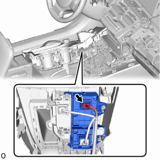
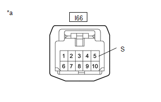
| (a) Disconnect the I66 integration control & panel assembly connector. |
|
| (b) Measure the voltage according to the value(s) in the table below. Standard Voltage:
|
|
(c) Reconnect the I66 integration control & panel assembly connector.
| NG | | GO TO STEP 7 |
|
| 6. | CHECK HARNESS AND CONNECTOR (INTEGRATION CONTROL & PANEL ASSEMBLY - BODY GROUND) |
(a) Disconnect the I66 integration control & panel assembly connector.
| (b) Measure the resistance according to the value(s) in the table below. Standard Resistance:
|
|

(c) Reconnect the I66 integration control & panel assembly connector.
| OK | | REPLACE INTEGRATION CONTROL & PANEL ASSEMBLY |
| NG | | REPAIR OR REPLACE HARNESS OR CONNECTOR |
| 7. | CHECK HARNESS AND CONNECTOR (HYBRID VEHICLE CONTROL ECU - INTEGRATION CONTROL & PANEL ASSEMBLY) |
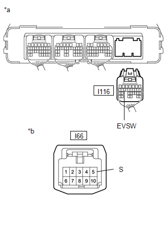
(a) Disconnect the I116 hybrid vehicle control ECU connector.
(b) Disconnect the I66 integration control & panel assembly connector.
| (c) Measure the resistance according to the value(s) in the table below. Standard Resistance:
|
|
(d) Reconnect the I66 integration control & panel assembly connector.
(e) Reconnect the I116 hybrid vehicle control ECU connector.
| OK | | REPLACE HYBRID VEHICLE CONTROL ECU |
| NG | | REPAIR OR REPLACE HARNESS OR CONNECTOR |
READ NEXT:
 Pattern Select Switch Sport Mode Circuit
DESCRIPTION When selecting SPORT mode, the switch operation signal is sent to the ECM. Following this, the drive torque is optimally controlled to obtain a sporty feel in response to the driver's acce
Pattern Select Switch Eco Mode Circuit
DESCRIPTION When selecting ECO mode, the mode switch (integration control & panel assembly) operation signal is sent to the air conditioning amplifier assembly. Following this, ECO mode control is
Indicator Circuit
DESCRIPTION In accordance with the shift lever position, each shift position indicator light will turn on. WIRING DIAGRAM PROCEDURE 1. CHECK SHIFT POSITION INDICATOR (a) Turn the power switc
SEE MORE:
Heated Oxygen Sensor
ComponentsCOMPONENTS ILLUSTRATION *1 FRONT EXHAUST PIPE SUB-ASSEMBLY *2 HEATED OXYGEN SENSOR *3 COMPRESSION SPRING *4 GASKET N*m (kgf*cm, ft.*lbf): Specified torque * For use with SST ● Non-reusable part - - RemovalREMOVAL PROCEDURE 1. REMOVE FRONT EXH
VC Output Circuit
DESCRIPTION The ECM constantly generates 5 V power source voltage from the auxiliary battery voltages supplied to the +B (BATT) terminal to operate the microprocessor. The ECM also provides this power source voltage to the sensors through the VC output circuit. When the VC circuit has a short circu
