Lexus NX: Inspection
INSPECTION
PROCEDURE
1. INSPECT TIRES
(a) Check the tires for wear and proper inflation pressure.
Specified Pressure (When Tire is Cool):
| Tire Size | Front kPa (kgf/cm2, psi) | Rear kPa (kgf/cm2, psi) |
|---|---|---|
| 225/65R17 102H | 240 (2.4, 35)*1 250 (2.5, 36)*2 | 240 (2.4, 35)*1 250 (2.5, 36)*2 |
| 225/60R18 100H | 220 (2.2, 32)*1 280 (2.9, 41)*2 | 220 (2.2, 32)*1 280 (2.9, 41)*2 |
*1: For driving at under 160 km/h (100 mph)
*2: For driving at over 160 km/h (100 mph)
Specified Pressure (When Tire is Cool) (for Compact Spare Tire):
| Tire Size | kPa (kgf/cm2, psi) |
|---|---|
| T165/80D17 104M | 420 (4.2, 60) |
(1) Tire pressure adjustment method when warm:
- Turn the power switch off.
- Connect the Techstream to the DLC3.
- Turn the power switch on (IG).
- Turn the Techstream on.
- Enter the following menus: Chassis / Tire Pressure Monitor / Data List.
- Adjust the tire pressure so that the displayed value is equal to the set pressure.
-
Perform initialization and check that initialization completes.
Click here
.gif)
- Check and record the value of the Data List item "Temperature in Tire". (Ts)
- Check and record the ambient temperature during tire pressure adjustment. (Tm)
-
Readjust the tire pressure according to the difference between the tire internal temperature (Ts) and the ambient temperature (Tm). (P)
HINT:
Tire internal temperature: Ts, Ambient temperature: Tm, Tire pressure readjustment value: PP = (Specified Pressure) + (Ts - Tm)
- Check the pressure adjustment value with the Data List item "Tire Inflation Pressure".
| Tester Display |
|---|
| ID 1 Tire Inflation Pressure |
| ID 2 Tire Inflation Pressure |
| ID 3 Tire Inflation Pressure |
| ID 4 Tire Inflation Pressure |
NOTICE:
Check the tire pressure warning system description for the relationship between the inflation pressure and tire pressure warning pressure.
Click here
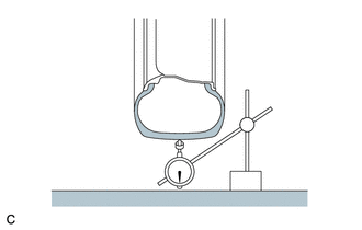
| (b) Using a dial indicator, check the runout of the tires. Tire runout: 1.4 mm (0.0551 in.) or less HINT: Remove the wheel assembly from the vehicle, and measure the wheel assembly alone. |
|
2. ROTATE TIRES
(a) Remove the wheel assembly.
Click here
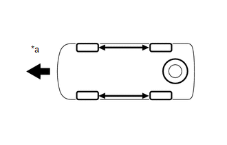
| (b) Rotate the tires as shown in the illustration. |
|
(c) Install the wheel assembly.
Click here
3. INSPECT WHEEL BALANCE
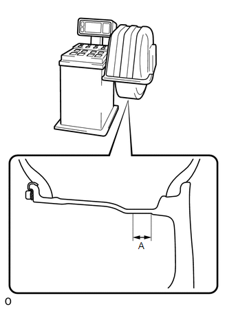
| (a) Check and adjust the off-the-car balance. Maximum imbalance after adjustment: 8.0 g (0.0176 lb.) NOTICE:
HINT:
|
|
4. INSPECT FRONT AXLE HUB BEARING LOOSENESS
Click here
5. INSPECT FRONT AXLE HUB RUNOUT
Click here
6. INSPECT REAR AXLE HUB BEARING LOOSENESS
Click here
7. INSPECT REAR AXLE HUB RUNOUT
Click here
READ NEXT:
 Tire Pressure Warning Initiator (for Front Side)
ComponentsCOMPONENTS ILLUSTRATION *1 FRONT TIRE PRESSURE MONITOR INITIATOR *2 CONNECTOR N*m (kgf*cm, ft.*lbf): Specified torque - - RemovalREMOVAL PROCEDURE 1. PRECAUTION CAU
SEE MORE:
Parts Location
PARTS LOCATION ILLUSTRATION *1 FRONT SEAT INNER BELT ASSEMBLY LH *2 FRONT SEAT OUTER BELT ASSEMBLY LH *3 OUTER MIRROR CONTROL ECU ASSEMBLY (for Driver Side) *4 NO. 2 ENGINE ROOM RELAY BLOCK
- MIRROR FUSE
- ECU-B NO.1 FUSE
ILLUSTRATION *1 SEAT MEMORY SWITCH *2
Noise Occurs
PROCEDURE 1. CHECK NOISE CONDITION (a) Check from which direction the noise comes (front left or right, or rear left or right). OK: The location of the noise source can be determined. NG GO TO STEP 3
OK 2. CHECK SPEAKERS (a) Check the installation condi
