Lexus NX: Removal
REMOVAL
CAUTION / NOTICE / HINT
HINT:
- Use the same procedure for the RH and LH sides.
- The procedure listed below is for the LH side.
PROCEDURE
1. PRECAUTION
NOTICE:
After the power switch off is turned off, there may be a waiting time before disconnecting the auxiliary negative (-) battery terminal.
Click here .gif)
2. REMOVE NO. 3 DECK BOARD SUB-ASSEMBLY
Click here
3. REMOVE REAR DECK FLOOR BOX
Click here
4. REMOVE DECK FLOOR BOX LH
Click here
5. DISCONNECT CABLE FROM NEGATIVE AUXILIARY BATTERY TERMINAL
NOTICE:
When disconnecting the cable, some systems need to be initialized after the cable is reconnected.
Click here
6. REMOVE REAR DOOR TRIM COVER LH
Click here
7. REMOVE REAR DOOR INSIDE HANDLE BEZEL PLUG LH
Click here
8. REMOVE REAR POWER WINDOW REGULATOR SWITCH ASSEMBLY WITH REAR DOOR ARMREST BASE PANEL
Click here
9. REMOVE REAR DOOR TRIM BOARD SUB-ASSEMBLY LH
Click here
10. REMOVE REAR DOOR INNER GLASS WEATHERSTRIP LH
Click here
11. REMOVE REAR DOOR ARMREST SET BRACKET LH
Click here
12. REMOVE REAR DOOR SERVICE HOLE COVER LH
Click here
13. REMOVE REAR DOOR GLASS RUN LH
Click here
14. DISCONNECT REAR DOOR CHECK ASSEMBLY LH
Click here
15. REMOVE REAR DOOR WEATHERSTRIP LH
Click here
16. REMOVE REAR DOOR FRAME GARNISH LH
Click here
17. REMOVE REAR DOOR REAR LOWER WINDOW FRAME SUB-ASSEMBLY LH
Click here
18. REMOVE REAR DOOR REAR GUIDE SEAL LH
Click here
19. REMOVE REAR DOOR GLASS SUB-ASSEMBLY LH
Click here
20. REMOVE REAR DOOR BELT MOULDING ASSEMBLY LH
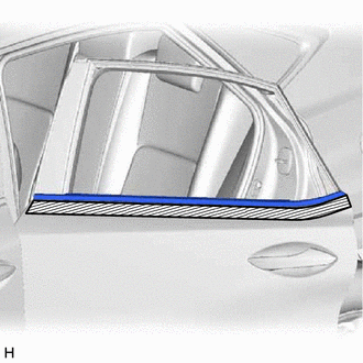
.png) | Protective Tape |
(a) Put protective tape around the rear door belt moulding assembly LH.
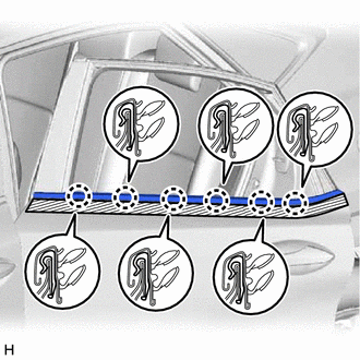
| (b) Using moulding remover D, detach the 6 claws and remove the rear door belt moulding assembly LH. |
|
READ NEXT:
 Installation
INSTALLATION CAUTION / NOTICE / HINT HINT:
Use the same procedure for the RH and LH sides.
The procedure listed below is for the LH side.
PROCEDURE 1. INSTALL REAR DOOR BELT MOULDING ASSEMBLY
Components
COMPONENTS ILLUSTRATION *1 OUTSIDE MOULDING RETAINER *2 REAR DOOR LOWER OUTSIDE MOULDING SUB-ASSEMBLY LH *3 REAR DOOR NO. 2 WEATHERSTRIP LH *4 REAR DOOR REAR UPPER OUTSIDE MOULDING
SEE MORE:
Installation
INSTALLATION PROCEDURE 1. INSTALL REAR SIDE SPOILER SUB-ASSEMBLY LH (a) Attach the 2 clips and guide to install the rear side spoiler sub-assembly LH. 2. INSTALL REAR SIDE SPOILER SUB-ASSEMBLY RH HINT: Use the same procedure described for the LH side. 3. INSTALL REAR SPOILER ASSEMBLY (a) Attach the
Precaution
PRECAUTION ADAPTIVE VARIABLE SUSPENSION SYSTEM PRECAUTION NOTICE:
Performing work after replacing the absorber control ECU with a normally functioning one from another vehicle may result in DTCs being stored, or have a negative effect on other systems. When replacing the absorber control ECU, be
