Lexus NX: Reassembly
REASSEMBLY
PROCEDURE
1. INSTALL NO. 1 BLOWER DAMPER SERVO SUB-ASSEMBLY
| (a) Install the link of the No. 1 blower damper servo sub-assembly to the link of the blower assembly as shown in the illustration. |
|
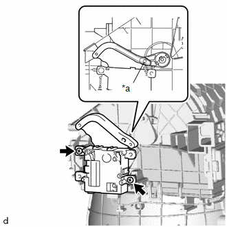
(b) Install the No. 1 blower damper servo sub-assembly with the 2 screws.
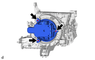
2. INSTALL BLOWER WITH FAN MOTOR SUB-ASSEMBLY
| (a) Install the blower with fan motor sub-assembly with the 3 screws. |
|
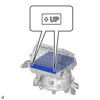
3. INSTALL AIR REFINER ELEMENT
| (a) Align the "UP" marks as shown in the illustration and install the air refiner element. |
|
4. INSTALL AIR FILTER CASE
| (a) Attach the guide and claw to install the air filter case. |
|
.png)
READ NEXT:
 Installation
INSTALLATION PROCEDURE 1. INSTALL BLOWER ASSEMBLY (a) Attach the 2 claws to install the blower assembly. (b) Install the 2 screws. (c) Attach the 3 clamps to install the air conditioning harness assem
Components
COMPONENTS ILLUSTRATION *1 BATTERY SERVICE HOLE COVER *2 HYBRID BATTERY SERVICE PLUG COVER *3 SERVICE PLUG GRIP - - N*m (kgf*cm, ft.*lbf): Specified torque - - ILLUST
SEE MORE:
Cooling Fan Ecu
On-vehicle InspectionON-VEHICLE INSPECTION PROCEDURE 1. INSPECT COOLING FAN ECU (a) Check and ensure the following conditions: (1) The power switch is off. (2) The engine coolant temperature is less than 92°C (198°F). (3) The auxiliary battery voltage is between 11 and 14 V. (4) The A/C switch is
Removal
REMOVAL PROCEDURE 1. REMOVE DOOR SCUFF PLATE ASSEMBLY LH Click here 2. REMOVE COWL SIDE TRIM BOARD LH Click here 3. REMOVE NO. 1 INSTRUMENT PANEL UNDER COVER SUB-ASSEMBLY Click here 4. REMOVE STOP LIGHT SWITCH ASSEMBLY (a) Disconnect the connector. (b) Loosen the lock
© 2016-2026 Copyright www.lexunx.com
